CAN 2.0 NETWORK CONTROLLER---MCAN2 PROGRAMMER’S GUIDE
-
INTRODUCTION
The Inventra? MCAN2 is a stand-alone controller for the CAN Controller Area Network used in the automotive industry and in
a number of other industrial environments. It provides an interface between a microprocessor and a CAN bus which carries out
all the actions of data encoding/decoding (including serialisation/deserialisation of data, bit stuffing/unstuffing), message
management (acceptance filtering, acknowledgement, error detection and signaling, and re-transmission), bit timing and
synchronization involved in transmitting and receiving information over a CAN network.
The MCAN2 controller implements the BOSCH CAN message transfer protocols 2.0A and 2.0B. Specification 2.0A (which is
equivalent to CAN 1.2) covers standard message formats (11-bit identifier); Specification 2.0B covers both standard and extended
message formats (both 11-bit and 29-bit identifiers).
The MCAN2 is broadly compatible with a Philips SJA1000 working in its PeliCAN mode (with some exceptions, detailed in
Section 8 of the MCAN2 Product Specification.).
The design has a synchronous PVCI1-compatible CPU interface for ease of connection to a range of microprocessor buses.
This document describes the software interface to the MCAN2 and describes how a typical application should drive the core. It
should be read in conjunction with the BOSCH CAN specification version 2.0 (hereafter referred to as the CAN 2.0
specification).
Note: The CAN 2.0 specification uses the convention that, on the CAN bus, Recessive bits are logic ‘1’ while Dominant bits are
logic ‘0’. This convention is also used in the MCAN2 design.
2 . M O D E S O F O P E R A T I O N
The MCAN2 has two main modes of operation: an Operating Mode in which data may be transmitted and received, and a Reset
Mode in which bus timing parameters and message acceptance filters can be set. Reset Mode also allows the Receive and
Transmit Error Counters and the Error Warning Limit to be changed.
Reset Mode is selected either by executing a hardware reset or by setting the Reset Mode bit in the Mode Register (MOD.0) to ‘1’.
The MCAN2 is returned to Operating Mode by clearing the MOD.0 bit. Note: Details of the Mode register may be found alongside the
details of the other MCAN2 registers in Section 10.
The MCAN2 also supports a Listen Only Mode and a Self Test Mode, selectable through the Mode Register in either Operating
Mode or Reset Mode.
In Listen Only Mode, the MCAN2 is only able to receive data: no transmission is possible. The MCAN2 does not even transmit
any acknowledgement of data being successfully received. It is also forced to be ‘error passive’. Note: This mode allows softwaredriven bit-rate detection, which in turn allows the MCAN2 to support ‘hot plug-in’ of the MCAN2 device – see Section 9.
In Self Test Mode, the MCAN2 sends and receives a message using the MCAN2’s Self Reception feature without looking for any
acknowledgement from any remote node.
The device also offers a Clock Output Mode, only selectable within Reset Mode, in which TX1 is used to output the Transmit
clock rather than a second copy of the transmission data. -
CONFIGURATION
The way in which the MCAN2 is configured to operate is set within its Reset Mode, into which it is placed both immediately
following a hardware reset (NRST taken low) and as a result of setting the Reset Mode bit in the Mode register (MOD.0) to 1
(software reset).
The details of the register settings following both these events are given in an Appendix at the end of this document.
While in Reset Mode, you may wish to set the following aspects of the MCAN2’s operation:
? The bus timing parameters to be applied (These select the baud rate used on the CAN bus)
? The acceptance filters to be applied to received messages
? The required interrupts
? The desired error warning limit
? The required output mode – with either a copy of the transmission bit stream or the Transmit clock on TX1
? The relationship of the CLKOUT signal to the input clock.
Further details are given in the following sections.
Note: The MCAN2 needs to be taken out of Reset Mode before any data can be sent or received.
3 .1 . B U S T IM IN G PAR AM E T E RS
The bus timing parameters configure the MCAN2 for the bit rate used on the CAN bus and set the point within each bit period
at which the received bit stream is to be sampled. They also specify the degree to which the MCAN2 may compensate for
variations in the bit rates generated by other nodes by re-synchronizing to the bit stream.
To cater for variations in the bit rate generated by other nodes and for physical delay times both on the bus and within the CAN
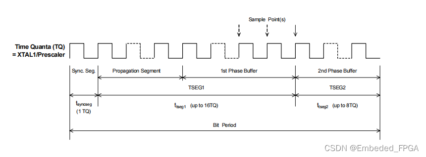
nodes, the bit period is seen as being composed of a Synchronization segment, a Propagation segment and two Phase Buffers.
The Synchronization segment represents the part of the bit period in which the bit edge is expected to arrive. The Propagation
segment represents the part of the bit time that is allowed to compensate for physical delay times. The two Phase Buffers
surround the sampling point and are shortened or lengthened as necessary to re-synchronize to the incoming bit stream when the
bit edge arrives outside of the Synchronization segment.
The length of each of these segments is defined as a number of ‘Time Quanta’ (TQ). The Synchronization segment is always
1 TQ, the Propagation segment may be 1 – 8 TQ, and the two Phase Buffers may be 1 – 8 TQ. The maximum amount by
which the Phase Buffers can be lengthened or shortened is also defined – as the Synchronization Jump Width. This is limited to
1 – 4 TQ and is also required to not be longer than either of the two Phase Buffers.
The timing parameters used on the MCAN2 are selected through the two Bus Timing Registers: BTR0 and BRT1.
BTR0 defines the time quantum to be used in terms of periods of the XTAL1 input clock, together with the Synchronization
Jump Width (in time quanta). Time quanta between 2 x the XTAL1 clock period and 128 x the XTAL1 clock period are
supported.
BTR1 defines the lengths in time quanta of two time segments, TSEG1 and TSEG2, and the number of samples made of each bit
period – 1 or 3 (1 is recommended for high-speed (class C) buses; 3 is recommended for low/medium (class A or B) buses).
TSEG1 represents the time between the Synchronization segment and the sample point (i.e. the Propagation segment plus the
first Phase Buffer). TSEG2 represents the time between the sample point and the end of the bit period (i.e. the second Phase
Buffer).
General Structure of a Bit Period

TSEG1 can be between 1 and 16 TQ long while TSEG2 can be between 1 and 8 TQ long. In theory, bit periods can therefore be
defined between 3 and 25 TQ in length. In practice, however, they are required to be in the range 8 and 25 TQ picked out by the
BOSCH standard.
Details of the BTR0 and BTR1 registers are given in Sections 10.4 and 10.5.
3.2. ACCEPTANCE FILTERS
Within a CAN network, all nodes receive all messages transmitted on the bus.
To allow a node to ignore messages that are not relevant to it, the MCAN2 provides a 4-byte Acceptance Filter, which can be
used to pick out only those messages with an appropriate identifier. Any message that does not pass though this filter can be
discarded as not applicable to the receiving CAN node.
Normally message filtering is based upon the whole identifier, which can be 11 or 29 bits long depending if the received message
is a standard or extended frame format. However, in the MCAN2, optional mask registers allow groups of identifiers to be
received and placed into the Receive FIFO by setting particular identifier bits to be ‘don’t care’.
The filter can be applied either as a single 4-byte filter or as two shorter filters. The selection is made through the AFM bit of the
Mode register (bit 3). If AFM = ‘1’, a single filter will be applied; if AFM = ‘0’, two filters will be applied. Where two filters are
used, the incoming message is accepted if its identifier matches either filter.
The filters applied are defined in a set of Acceptance Code Registers ACR0 – 3, used in conjunction with a corresponding set of
Acceptance Mask Registers AMR0 – 3 (see Sections 10.1 and 10.2). The bit pattern against which the message identifier is
matched is recorded in the ACR registers, masked by the values recorded in the AMR registers. ‘0’s in AMR0 – 3 identify the bits
at the corresponding positions in ACR0 – 3 which must be matched in the message identifier, ‘1’s identify the corresponding bits
as ‘don’t care’. Both groups of registers are set to zero by a hardware reset (i.e. set to accept only messages with a zero identifier)
but are left unchanged by a software reset.
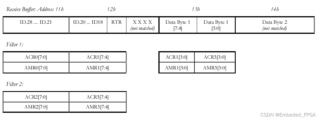
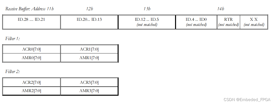
The way in which the bit patterns defined by ACR0 – 3 are applied further depend on whether the incoming message is in
Standard Frame Format (SFF) or Extended Frame Format (EFF) as shown on the following page:
Standard Frame Format, Single Filter:

Note: If matching of the data bytes is not required, AMR2 and AMR3 should be set to FFh.
Standard Frame Format, Dual Filters

Extended Frame Format, Single Filter

Extended Frame Format, Dual Filters

3.3. INTERRRUPTS
The MCAN2 supports the generation of an interrupt for any of the following conditions:
? Bus activity while the MCAN2 is in Sleep Mode (Wake-Up Interrupt)
? Receipt of a message (Receive Interrupt)
? Completion of the current transmission (Transmit Interrupt)
? Loss of Received data through the FIFO being full (Data Overrun Interrupt)
? Loss of Arbitration on the CAN bus* (Arbitration Loss Interrupt)
? Error on the CAN bus* (Bus Error Interrupt)
? MCAN2 coming out of ‘Error Passive’ state (Error Passive Interrupt)
? The number of errors either exceeding the Error Warning Limit or causing the device to go into Bus Off state (Error
Warning Interrupt)
Following a hardware reset, these interrupts are disabled. The user therefore needs to enable the ones they require in the Interrupt
Enable Register (described in Section 10.11). The selection of interrupts that are enabled is not however affected by a software
reset.
- Note: There is not normally any need for the CPU to monitor Loss of Arbitration events or individual bus errors as the
MCAN2 will automatically retry transmission when these happen.
本文来自互联网用户投稿,该文观点仅代表作者本人,不代表本站立场。本站仅提供信息存储空间服务,不拥有所有权,不承担相关法律责任。 如若内容造成侵权/违法违规/事实不符,请联系我的编程经验分享网邮箱:veading@qq.com进行投诉反馈,一经查实,立即删除!