Kubernetes-网络

一. 前言
-
flannel两种容器跨主机通信的方案,其中UDP模式是IP in UDP,即三层报文封装在UDP数据包中通信;而vxlan模式则是MAC in UDP,即二层报文封装在UDP数据包中通信 -
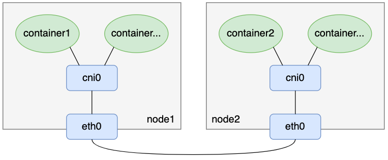
flannel UDP模式和vxlan模式都对数据包做了封解包,特别是UDP模式,还涉及到用户态和内核态数据切换,在性能上肯定存在一定的损耗。本文介绍flannel另外一种没有封解包的容器跨主机通信方案:flannel host-gateway模式,相比于UDP和vxlan模式,host-gateway模式没有额外的封解包过程,单纯依靠路由表项配置实现容器跨主机通信网络。其模型如下图:
1. 二层互通与三层互通
在开始之前,我们先来简单了解二层互通与三层互通:
-
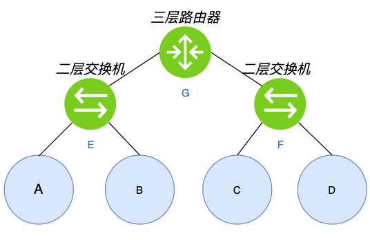
如上图所示,其中A、B、C、D是四台主机,E、F是两台二层交换机(根据MAC转发),G是三层路由器(根据IP转发)。
-
假设从A发出一个数据包,这个包到达E这台二层交换机后,如果E上没有目标MAC与端口的对应关系,就会将这个数据包往入口外的其它端口转发该报文,也就是E会把这个报文发给B和G。如果该数据包的目标MAC是B,那么B能正常处理该数据包,此时我们把A和B叫作“二层互通”;而如果目的MAC是C或者D(例如A上有一条网关是C或者D的路由),B和G收到数包后会因目的MAC不是自己而丢掉该数据包,此时A和C或者D都不通,我们把这种场景叫作“二层不互通”。
-
假设从A要访问C,G是A的默认网关,即A发出一个目的IP是C但MAC是G的数据包。这个数据包到达G时,G发现MAC是自己,于是根据相关机制找到C并把报文经过F这台二层交换机转发给C,A与C能正常通信,此时A与C叫作“三层互通”(但“二层不互通”)。
2. Linux支持的三层隧道
- linux原生共支持5种三层隧道,这些三层隧道底层实现原理都是基于tun设备
- ipip:IPv4 in IPv4,在IPv4报文的基础上封装一个IPv4报文
- GRE:Generic Routing Encapsulation,通用路由封装,适用于IPv4和IPv6(腾讯TKE的vpc-cni中使用的就是这种隧道)
- sit:IPv6 over IPv4,即IPv4报文封装IPv6报文
- ISATAP:Intra Site Automatic Tunnel Addressing Protocol,站内自动隧道寻址协议,与sit类似,也用于IPv6的隧道封装
- VTL:Virtual Tunnel Interface,思科提出的一种IPSec隧道技术
二. host-gateway
- 要是新host-gateway模式, 有了以上知识,需要准备如下环境
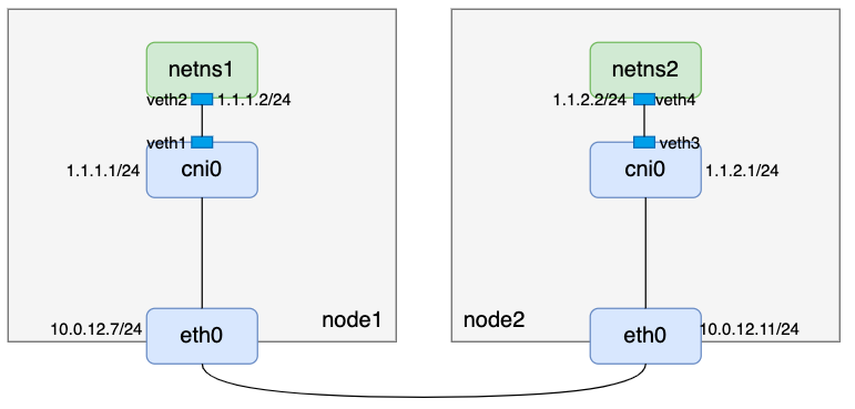
说明:
- 两台机器均已打开内核ipv4转发开关
- 容器分配的IP网段为1.1.0.0/16
- node1维护1.1.1.0/24 IP段
- node2维护1.1.2.0/24 IP段
- 两台主机二层互通
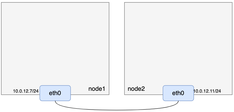
1. 准备两台二层互通的主机
- 准备如下两台二层互通的机器
2. netns, veth pair和linux brdge
- 准备netns、veth pair、linux bridge:
// node1
// 创建网络命名空间netns1
[root@VM-12-11-centos ~]# ip netns add netns1
// 创建虚拟网络设备对veth1-veth2
[root@VM-12-11-centos ~]# ip link add veth1 type veth peer name veth2
// 把veth2放入网络命名空间netns1
[root@VM-12-11-centos ~]# ip link set veth2 netns netns1
// 给veth2配置IP并up
[root@VM-12-11-centos ~]# ip netns exec netns1 ifconfig veth2 1.1.1.2/24 up
// 创建cni0网桥设备
[root@VM-12-11-centos ~]# ip link add name cni0 type bridge
// 给cni0配置IP并up
[root@VM-12-11-centos ~]# ifconfig cni0 1.1.1.1/24 up
// veth1连接cni0
[root@VM-12-11-centos ~]# ip link set dev veth1 master cni0
// 设备veth1 up
[root@VM-12-11-centos ~]# ifconfig veth1 up
// 增加默认路由
[root@VM-12-11-centos ~]# ip netns exec netns1 ip route add default via 1.1.1.1 dev veth2
// 查看netns1路由
[root@VM-12-11-centos ~]# ip netns exec netns1 route -n
Kernel IP routing table
Destination     Gateway         Genmask         Flags Metric Ref    Use Iface
0.0.0.0         1.1.1.1         0.0.0.0         UG    0      0        0 veth2
1.1.1.0         0.0.0.0         255.255.255.0   U     0      0        0 veth2


// node2
// 创建网络命名空间netns2
[root@VM-12-7-centos ~]# ip netns add netns2
// 创建虚拟网络设备对veth3-veth4
[root@VM-12-7-centos ~]# ip link add veth3 type veth peer name veth4
// 把veth4放入网络命名空间netns2
[root@VM-12-7-centos ~]# ip link set veth4 netns netns2
// 给veth4配置IP并up
[root@VM-12-7-centos ~]# ip netns exec netns2 ifconfig veth4 1.1.2.2/24 up
// 创建cni0网桥设备
[root@VM-12-7-centos ~]# ip link add name cni0 type bridge
// 给cni0配置IP并up
[root@VM-12-7-centos ~]# ifconfig cni0 1.1.2.1/24 up
// veth3连接cni0
[root@VM-12-7-centos ~]# ip link set dev veth3 master cni0
// 设置veth3 up
[root@VM-12-7-centos ~]# ifconfig veth3 up
// 增加默认路由
[root@VM-12-7-centos ~]# ip netns exec netns2 ip route add default 1.1.2.1 dev veth4
// 查看netns2路由
[root@VM-12-7-centos ~]# ip netns exec netns2 route -n
Kernel IP routing table
Destination     Gateway         Genmask         Flags Metric Ref    Use Iface
0.0.0.0         1.1.2.1         0.0.0.0         UG    0      0        0 veth4
1.1.2.0         0.0.0.0         255.255.255.0   U     0      0        0 veth4
- 到这里,我们先看看当前宿主机上的路由:
// node1
[root@VM-12-11-centos ~]# route -n
Kernel IP routing table
Destination     Gateway         Genmask         Flags Metric Ref    Use Iface
0.0.0.0         10.0.12.1       0.0.0.0         UG    0      0        0 eth0
1.1.1.0         0.0.0.0         255.255.255.0   U     0      0        0 cni0
10.0.12.0       0.0.0.0         255.255.252.0   U     0      0        0 eth0

// node2
[root@VM-12-7-centos ~]# route -n
Kernel IP routing table
Destination     Gateway         Genmask         Flags Metric Ref    Use Iface
0.0.0.0         10.0.12.1       0.0.0.0         UG    0      0        0 eth0
1.1.2.0         0.0.0.0         255.255.255.0   U     0      0        0 cni0
10.0.12.0       0.0.0.0         255.255.252.0   U     0      0        0 eth0
- 根据路由规则,此时node1上可以ping通1.1.1.2,node2上可以ping通1.1.2.2,但是node1上ping不通1.1.2.2,node2上也ping不通node1上1.1.1.2:
// node1
[root@VM-12-11-centos ~]# ping -c 1 1.1.1.2
PING 1.1.1.2 (1.1.1.2) 56(84) bytes of data.
64 bytes from 1.1.1.2: icmp_seq=1 ttl=64 time=0.038 ms

--- 1.1.1.2 ping statistics ---
1 packets transmitted, 1 received, 0% packet loss, time 0ms
rtt min/avg/max/mdev = 0.038/0.038/0.038/0.000 ms
[root@VM-12-11-centos ~]# ping -c 1 1.1.2.2
PING 1.1.2.2 (1.1.2.2) 56(84) bytes of data.

--- 1.1.2.2 ping statistics ---
1 packets transmitted, 0 received, 100% packet loss, time 0ms


// node2
[root@VM-12-7-centos ~]# ping -c 1 1.1.2.2
PING 1.1.2.2 (1.1.2.2) 56(84) bytes of data.
64 bytes from 1.1.2.2: icmp_seq=1 ttl=64 time=0.019 ms

--- 1.1.2.2 ping statistics ---
1 packets transmitted, 1 received, 0% packet loss, time 0ms
rtt min/avg/max/mdev = 0.019/0.019/0.019/0.000 ms
[root@VM-12-7-centos ~]# ping -c 1 1.1.1.2
PING 1.1.1.2 (1.1.1.2) 56(84) bytes of data.

--- 1.1.1.2 ping statistics ---
1 packets transmitted, 0 received, 100% packet loss, time 0ms
- 所以现在我们的整体逻辑还是这样:
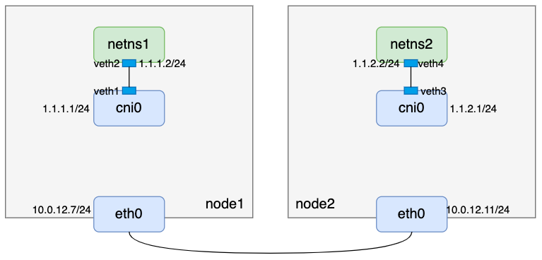
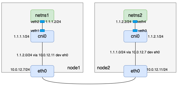
- 因为node1和node2 二层互通,在node1上访问node2上的1.1.2.2,可以考虑添加一条网关是node2 eth0 IP的路由;考虑回程报文,node2也应该加一条网关是node1 eth0 IP的路由,于是有:
// node1
[root@VM-12-11-centos ~]# ip route add 1.1.2.0/24 via 10.0.12.7 dev eth0
[root@VM-12-11-centos ~]# route -n
Kernel IP routing table
Destination     Gateway         Genmask         Flags Metric Ref    Use Iface
0.0.0.0         10.0.12.1       0.0.0.0         UG    0      0        0 eth0
1.1.1.0         0.0.0.0         255.255.255.0   U     0      0        0 cni0
1.1.2.0         10.0.12.7       255.255.255.0   UG    0      0        0 eth0
10.0.12.0       0.0.0.0         255.255.252.0   U     0      0        0 eth0

// node2
[root@VM-12-7-centos ~]# ip route add 1.1.1.0/24 via 10.0.12.11 dev eth0
[root@VM-12-7-centos ~]# route -n
Kernel IP routing table
Destination     Gateway         Genmask         Flags Metric Ref    Use Iface
0.0.0.0         10.0.12.1       0.0.0.0         UG    0      0        0 eth0
1.1.1.0         10.0.12.11      255.255.255.0   UG    0      0        0 eth0
1.1.2.0         0.0.0.0         255.255.255.0   U     0      0        0 cni0
10.0.12.0       0.0.0.0         255.255.252.0   U     0      0        0 eth0
此时整体逻辑才算打通
3. 验证
- 在node1上ping node2上的1.1.2.2以及在node2上ping node1上的1.1.1.2
// node1
[root@VM-12-11-centos ~]# ping -c 1 1.1.2.2
PING 1.1.2.2 (1.1.2.2) 56(84) bytes of data.
64 bytes from 1.1.2.2: icmp_seq=1 ttl=64 time=0.040 ms

--- 1.1.2.2 ping statistics ---
1 packets transmitted, 1 received, 0% packet loss, time 0ms
rtt min/avg/max/mdev = 0.040/0.040/0.040/0.000 ms
[root@VM-12-11-centos ~]# ip netns exec netns1 ping -c 1 1.1.2.2
PING 1.1.2.2 (1.1.2.2) 56(84) bytes of data.
64 bytes from 1.1.2.2: icmp_seq=1 ttl=64 time=0.019 ms

--- 1.1.2.2 ping statistics ---
1 packets transmitted, 1 received, 0% packet loss, time 0ms
rtt min/avg/max/mdev = 0.019/0.019/0.019/0.000 ms


// node2
[root@VM-12-7-centos ~]# ping -c 1 1.1.1.2
PING 1.1.1.2 (1.1.1.2) 56(84) bytes of data.
64 bytes from 1.1.1.2: icmp_seq=1 ttl=64 time=0.026 ms

--- 1.1.1.2 ping statistics ---
1 packets transmitted, 1 received, 0% packet loss, time 0ms
rtt min/avg/max/mdev = 0.026/0.026/0.026/0.000 ms
[root@VM-12-7-centos ~]# ip netns exec netns2 ping -c 1 1.1.1.2
PING 1.1.1.2 (1.1.1.2) 56(84) bytes of data.
64 bytes from 1.1.1.2: icmp_seq=1 ttl=64 time=0.024 ms

--- 1.1.1.2 ping statistics ---
1 packets transmitted, 1 received, 0% packet loss, time 0ms
rtt min/avg/max/mdev = 0.024/0.024/0.024/0.000 ms
4. host-gateway特性
-
flannel host-gateway模式正如host-gateway的含义,通过一条目标主机(host)IP作为网关(gateway)的路由实现容器跨主机通信。相比于UDP模式和vxlan模式,少了tun设备和vxlan设备的封解包过程,在性能上有更大的优势。但是直连路由要求主机间二层互通,这在一定程度上限制了host-gateway的使用场景,特别是公有云环境,不太好满足所有节点二层互通的条件。
-
上文的路由是手动配置的,在flannel的实现中,是通过flanneld进程完成该操作的:每个节点上起一个flanneld进程,flanneld进程起来后注册本节点管理的网段和宿主机IP等信息到etcd(直连etcd或者通过apiServer接口),并且监听其它节点的注册信息,当发现有新节点加入集群时,便会在本节点增加一条网关是新节点IP的路由。
5. UDP, VXLAN, Host-Gateway对比
- 到这里我们已经了解了flannel UDP、vxlan和host-gateway三种模式的原理,我们再对比一下这三种模式
| 对比项 | UDP模式 | vxlan模式 | host-gateway模式 |
|---|---|---|---|
| 网络模式 | overlay | overlay | underlay |
| 封解包设备/程序 | tun+flanneld | vxlan | 无 |
| 节点间网络要求 | 三层互通 | 三层互通 | 二层互通 |
| 性能 | 最差 | 中等 | 最快 |
| flanneld的作用 | UDP封解包;监听节点变化 | 监听节点变化,维护路由、ARP和FDB表项 | 监听节点变化,维护路由信息 |
二. VXLAN
- flannel vxlan模式是一种基于vxlan设备在内核中封解包实现overlay网络的方法, 如果说flannel UDP模式是IP in UDP(IP数据包封装在UDP数据包中,也就是三层网络的基础上构建一个虚拟的三层网络),那么flannel vxlan模式就是MAC in UDP(链路层数据封装在UDP数据包中,也就是三层网络的基础上构建一个虚拟的二层网络),也是flannel默认模式
- vxlan模式其实就是各宿主机上的
Flannel.1设备组成的虚拟二层网络
1. 理论准备
- vlan(Virtual Local Area Network)虚拟局域网络技术,vlan数据包的头部预留了12bit来标识子网,也就是最多只能支持2^12=4096个子网的划分,这无法满足云计算场景下的需求。vxlan(Virtual eXtensible Local Area Network)技术是对vlan的扩展,vxlan头部有24bit来标识子网,也就是最多可以划分2^24=16777216个子网,理论上可以支撑千万量级别子网的云计算场景。vxlan报文格式如下:
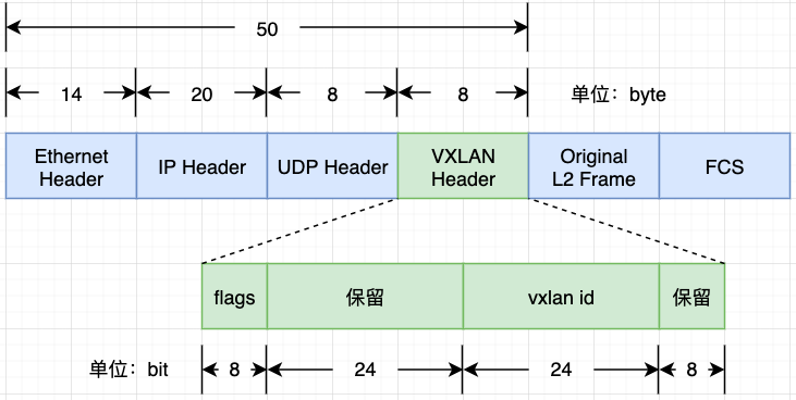
- 从图中可以看出,vxlan报文比原始报文多了50个字节数据,所以我们通过ifconfig命令看到vxlan设备的MTU一般是1450,比一般网络设备默认的MTU 1500小50个字节:
[root@VM-12-11-centos ~]# ifconfig vxlan0
vxlan0: flags=4163<UP,BROADCAST,RUNNING,MULTICAST>  mtu 1450
        inet 172.1.1.1  netmask 255.255.255.0  broadcast 172.1.1.255
        inet6 fe80::2c4d:5eff:fe39:5f92  prefixlen 64  scopeid 0x20<link>
        ether 2e:4d:5e:39:5f:92  txqueuelen 1000  (Ethernet)
        RX packets 0  bytes 0 (0.0 B)
        RX errors 0  dropped 0  overruns 0  frame 0
        TX packets 0  bytes 0 (0.0 B)
        TX errors 0  dropped 6 overruns 0  carrier 0  collisions 0
本文还需了解两个与vxlan有关的概念:
- VNI:每个vxlan子网通过唯一的VNI来标识区分,该标识是个24bit范围的整数
- VTEP:VXLAN Tunnel Endpoints,即vxlan网络的边缘设备,为了方便理解,本文把VTEP设备也叫作“vxlan设备”。VNI配置在VTEP设备上,VNI相同的VTEP设备属于同一个vxlan子网网络
2. UDP vs VXLAN
- flannel UDP模式
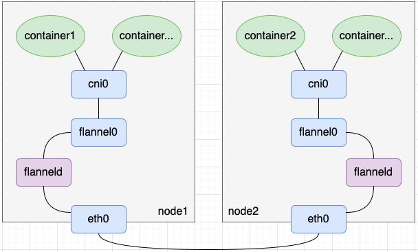
- 在flannel UDP模式中,我们创建了tun设备flannel0以及启动了该tun设备关联的用户态程序flanneld,并在用户态程序flanneld中编码实现了报文的封解包。相比flannel UDP模式,flannel vxlan模式用了一个vxlan设备flannel.1替换了flannel0+flanneld的封解包工作(这句话不是很严谨,读者理解即可)。如下图所示,其中flannel在命名vxlan设备时,规则为flannel.{VNI},所以flannel.1设备的VNI就是1
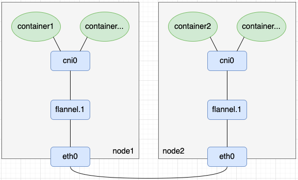
- 可以用ip -d link show命令查看vxlan设备的VNI,显示信息中vxlan id后面的数字就是VNI的值:
[root@VM-12-11-centos ~]# ip -d link show vxlan0
33: vxlan0: <BROADCAST,MULTICAST,UP,LOWER_UP> mtu 1450 qdisc noqueue state UNKNOWN mode DEFAULT group default qlen 1000
   link/ether 2e:4d:5e:39:5f:92 brd ff:ff:ff:ff:ff:ff promiscuity 0
   vxlan id 1 dev eth0 srcport 0 0 dstport 1111 ageing 300 noudpcsum noudp6zerocsumtx noudp6zerocsumrx addrgenmode eui64 numtxqueues 1 numrxqueues 1 gso_max_size 65536 gso_max_segs 65535
3. 环境准备
- 根据前面的知识,我们准备如下环境:
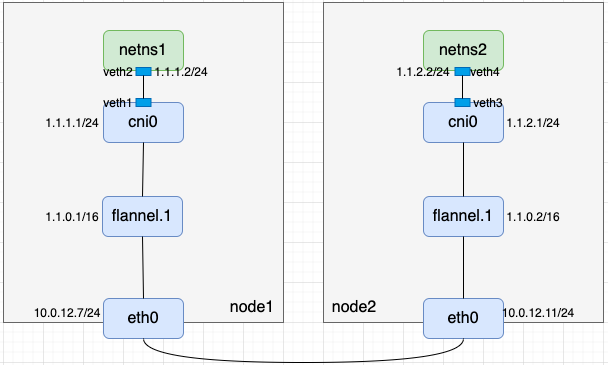
说明:
- 两台机器的8472端口开放了UDP的防火墙
- 两台机器均已打开内核ipv4转发开关
- 容器分配的IP网段为1.1.0.0/16
- flannel.1是vxlan设备,且该vxlan设备的VNI为1
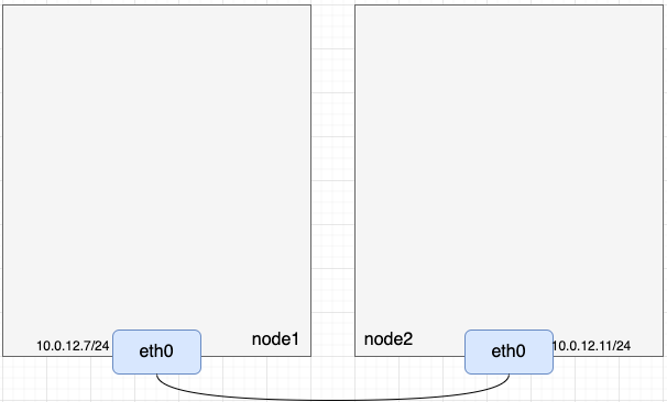
(1). 准备宿主机
- 当前宿主机信息如下:
(2). 准备vxlan设备flannel.1
- 我们可以用ip link add flannel.1 type vxlan id 1 dstport 8472 dev eth0命令创建vxlan设备,对这条命令解释一下
- add flannel.1 type vxlan:创建名称为flannel.1的vxlan设备
- id 1:设置vxlan设备的VNI为1
- dstport 8472:vxlan设备是把二层数据包封装在UDP中发出去,同时也要起个UDP server来接收其它vxlan设备发过来的数据,这里配置的就是UDP server的端口
- dev eth0:指定vxlan外层出口,即最终封装好的UDP数据从宿主机的哪个口出去
// node1
// 创建vxlan设备flannel.1
[root@VM-12-11-centos ~]# ip link add flannel.1 type vxlan id 1 dstport 8472 dev eth0
// 配置IP并up
[root@VM-12-11-centos ~]# ifconfig flannel.1 1.1.0.1/16 up
// 查看vxlan设备信息
[root@VM-12-11-centos ~]# ifconfig flannel.1
flannel.1: flags=4163<UP,BROADCAST,RUNNING,MULTICAST>  mtu 1450
        inet 1.1.0.1  netmask 255.255.0.0  broadcast 1.1.255.255
        inet6 fe80::7c06:12ff:fe29:250a  prefixlen 64  scopeid 0x20<link>
        ether 7e:06:12:29:25:0a  txqueuelen 1000  (Ethernet)
        RX packets 0  bytes 0 (0.0 B)
        RX errors 0  dropped 0  overruns 0  frame 0
        TX packets 0  bytes 0 (0.0 B)
        TX errors 0  dropped 7 overruns 0  carrier 0  collisions 0
// 查看路由信息
[root@VM-12-11-centos ~]# route -n
Kernel IP routing table
Destination     Gateway         Genmask         Flags Metric Ref    Use Iface
0.0.0.0         10.0.12.1       0.0.0.0         UG    0      0        0 eth0
1.1.0.0         0.0.0.0         255.255.0.0     U     0      0        0 flannel.1
10.0.12.0       0.0.0.0         255.255.252.0   U     0      0        0 eth0

// node2
// 创建vxlan设备flannel.1
[root@VM-12-7-centos ~]# ip link add flannel.1 type vxlan id 1 dstport 8472 dev eth0
// 配置IP并up
[root@VM-12-7-centos ~]# ifconfig flannel.1 1.1.0.2/16 up
// 查看vxlan设备信息
[root@VM-12-7-centos ~]# ifconfig flannel.1
flannel.1: flags=4163<UP,BROADCAST,RUNNING,MULTICAST>  mtu 1450
        inet 1.1.0.2  netmask 255.255.0.0  broadcast 1.1.255.255
        inet6 fe80::24ba:90ff:fe73:3993  prefixlen 64  scopeid 0x20<link>
        ether 26:ba:90:73:39:93  txqueuelen 1000  (Ethernet)
        RX packets 0  bytes 0 (0.0 B)
        RX errors 0  dropped 0  overruns 0  frame 0
        TX packets 0  bytes 0 (0.0 B)
        TX errors 0  dropped 8 overruns 0  carrier 0  collisions 0
// 查看路由信息
[root@VM-12-7-centos ~]# route -n
Kernel IP routing table
Destination     Gateway         Genmask         Flags Metric Ref    Use Iface
0.0.0.0         10.0.12.1       0.0.0.0         UG    0      0        0 eth0
1.1.0.0         0.0.0.0         255.255.0.0     U     0      0        0 flannel.1
10.0.12.0       0.0.0.0         255.255.252.0   U     0      0        0 eth0
- 在vxlan设备up后,用netstat -nulp命令可以看到宿主机上监听了8472端口,最后一列的“-”表示这个端口是内核态程序监听的而不是用户态程序监听的
[root@VM-12-11-centos ~]# netstat -nulp | grep 8472
udp        0      0 0.0.0.0:8472            0.0.0.0:*                           -
- 到这里,node1上的flannel.1和node2上的flannel.1虽然都有了IP但还是无法通信,那是因为vxlan设备封解包还有两个问题需要解决
- 内层报文是二层报文,需要知道对方vxlan设备的MAC地址
- 外层报文需要知道对方vxlan设备宿主机IP,否则无法确定该UDP数据包发往哪台机器
- 对于第一个问题,已知对方IP求对方MAC的解法,很容易想到ARP记录,我们可以通过如下命令把对方vxlan设备的MAC信息写到ARP记录里
// node1
[root@VM-12-11-centos ~]# arp -i flannel.1 -s 1.1.0.2 26:ba:90:73:39:93
[root@VM-12-11-centos ~]# ip neigh show dev flannel.1
1.1.0.2 lladdr 26:ba:90:73:39:93 PERMANENT

// node2
[root@VM-12-7-centos ~]# arp -i flannel.1 -s 1.1.0.1 7e:06:12:29:25:0a
[root@VM-12-7-centos ~]# ip neigh show dev flannel.1
1.1.0.1 lladdr 7e:06:12:29:25:0a PERMANENT
- 接下来是第二个问题,基于第一个问题的解决方案,我们现在知道了对方vxlan设备的IP和MAC,需要知道对方宿主机IP。这里补充个知识点:网络设备维护了一张MAC地址与端口对应的表以便交换机内部实现二层数据转发,这张二层转发表叫作FDB表。我们可以在FDB表中添加目标vxlan设备MAC与目标主机IP的对应关系:
// node1
[root@VM-12-11-centos ~]# bridge fdb append 26:ba:90:73:39:93 dev flannel.1 dst 10.0.12.7
[root@VM-12-11-centos ~]# bridge fdb show dev flannel.1
26:ba:90:73:39:93 dst 10.0.12.7 self permanent

// node2
[root@VM-12-7-centos ~]# bridge fdb append 7e:06:12:29:25:0a dev flannel.1 dst 10.0.12.11
[root@VM-12-7-centos ~]# bridge fdb show dev flannel.1
7e:06:12:29:25:0a dst 10.0.12.11 self permanent
-
重新梳理下:vxlan设备1需要访问vxlan设备2时,先通过对方IP从ARP记录里找到对方MAC地址填充到内层报文中,再通过对方MAC地址从FDB表中查找到对方宿主机IP填充到外层报文中,这样就完成了封包过程。回包过程类似过程,不再赘述
-
验证下node1上flannel.1和node2上flannel.1是否已互通
// node1
[root@VM-12-11-centos ~]# ping -c 1 1.1.0.2
PING 1.1.0.2 (1.1.0.2) 56(84) bytes of data.
64 bytes from 1.1.0.2: icmp_seq=1 ttl=64 time=0.208 ms

--- 1.1.0.2 ping statistics ---
1 packets transmitted, 1 received, 0% packet loss, time 0ms
rtt min/avg/max/mdev = 0.208/0.208/0.208/0.000 ms


// node2
[root@VM-12-7-centos ~]# ping -c 1 1.1.0.1
PING 1.1.0.1 (1.1.0.1) 56(84) bytes of data.
64 bytes from 1.1.0.1: icmp_seq=1 ttl=64 time=0.221 ms

--- 1.1.0.1 ping statistics ---
1 packets transmitted, 1 received, 0% packet loss, time 0ms
rtt min/avg/max/mdev = 0.221/0.221/0.221/0.000 ms
- 到这里我们完成了如下逻辑,逻辑上像是在node1和node2上建了一条隧道
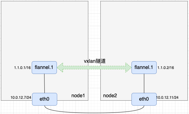
(3)准备netns, veth pair和bridge
- 准备netns、veth pair和bridge,相关命令如下
// node1
// 创建网络命名空间netns1
[root@VM-12-11-centos ~]# ip netns add netns1
// 创建虚拟网络设备对veth1-veth2
[root@VM-12-11-centos ~]# ip link add veth1 type veth peer name veth2
// 把veth2放入网络命名空间netns1
[root@VM-12-11-centos ~]# ip link set veth2 netns netns1
// 给veth2配置IP并up
[root@VM-12-11-centos ~]# ip netns exec netns1 ifconfig veth2 1.1.1.2/24 up
// 增加默认路由
[root@VM-12-11-centos ~]# ip netns exec netns1 ip route add default via 1.1.1.1 dev veth2
// 查看netns1路由
[root@VM-12-11-centos ~]# ip netns exec netns1 route -n
Kernel IP routing table
Destination     Gateway         Genmask         Flags Metric Ref    Use Iface
0.0.0.0         1.1.1.1         0.0.0.0         UG    0      0        0 veth2
1.1.1.0         0.0.0.0         255.255.255.0   U     0      0        0 veth2

// node2
// 创建网络命名空间netns2
[root@VM-12-7-centos ~]# ip netns add netns2
// 创建虚拟网络设备对veth3-veth4
[root@VM-12-7-centos ~]# ip link add veth3 type veth peer name veth4
// 把veth4放入网络命名空间netns2
[root@VM-12-7-centos ~]# ip link set veth4 netns netns2
// 给veth4配置IP并up
[root@VM-12-7-centos ~]# ip netns exec netns2 ifconfig veth4 1.1.2.2/24 up
// 增加默认路由
[root@VM-12-7-centos ~]# ip netns exec netns2 ip route add default 1.1.2.1 dev veth4
// 查看netns2路由
[root@VM-12-7-centos ~]# ip netns exec netns2 route -n
Kernel IP routing table
Destination     Gateway         Genmask         Flags Metric Ref    Use Iface
0.0.0.0         1.1.2.1         0.0.0.0         UG    0      0        0 veth4
1.1.2.0         0.0.0.0         255.255.255.0   U     0      0        0 veth4
- 通过上述命令我们完成了如下逻辑
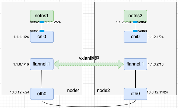
- 不难发现node1上从cni0出来访问1.1.2.0/24的流量应该到node1上flannel.1,再从node2上flannel.1出来;而对node2来说,往1.1.1.0/24的流量也应该到node2上flannel.1,再从node1上的flannel.1出来。因此应该在两个节点上各加一条带有网关的路由
// node1
[root@VM-12-11-centos ~]# ip route add 1.1.2.0/24 via 1.1.0.2 dev flannel.1
[root@VM-12-11-centos ~]# route -n
Kernel IP routing table
Destination     Gateway         Genmask         Flags Metric Ref    Use Iface
0.0.0.0         10.0.12.1       0.0.0.0         UG    0      0        0 eth0
1.1.0.0         0.0.0.0         255.255.0.0     U     0      0        0 flannel.1
1.1.1.0         0.0.0.0         255.255.255.0   U     0      0        0 cni0
1.1.2.0         1.1.0.2         255.255.255.0   UG    0      0        0 flannel.1
10.0.12.0       0.0.0.0         255.255.252.0   U     0      0        0 eth0

// node2
[root@VM-12-7-centos ~]# ip route add 1.1.1.0/24 via 1.1.0.1 dev flannel.1
[root@VM-12-7-centos ~]# route -n
Kernel IP routing table
Destination     Gateway         Genmask         Flags Metric Ref    Use Iface
0.0.0.0         10.0.12.1       0.0.0.0         UG    0      0        0 eth0
1.1.0.0         0.0.0.0         255.255.0.0     U     0      0        0 flannel.1
1.1.1.0         1.1.0.1         255.255.255.0   UG    0      0        0 flannel.1
1.1.2.0         0.0.0.0         255.255.255.0   U     0      0        0 cni0
10.0.12.0       0.0.0.0         255.255.252.0   U     0      0        0 eth0
- 至此整条链路已串联起来
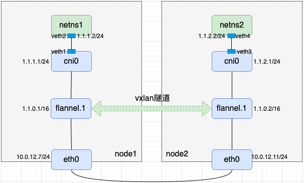
- 我们用node1上netns1和node2上netns2互ping来验证链路联通性
// node1
[root@VM-12-11-centos ~]# ip netns exec netns1 ping -c 1 1.1.2.2
PING 1.1.2.2 (1.1.2.2) 56(84) bytes of data.
64 bytes from 1.1.2.2: icmp_seq=1 ttl=62 time=0.250 ms

--- 1.1.2.2 ping statistics ---
1 packets transmitted, 1 received, 0% packet loss, time 0ms
rtt min/avg/max/mdev = 0.250/0.250/0.250/0.000 ms


// node2
[root@VM-12-7-centos ~]# ip netns exec netns2 ping -c 1 1.1.1.1
PING 1.1.1.1 (1.1.1.1) 56(84) bytes of data.
64 bytes from 1.1.1.1: icmp_seq=1 ttl=63 time=0.235 ms

--- 1.1.1.1 ping statistics ---
1 packets transmitted, 1 received, 0% packet loss, time 0ms
rtt min/avg/max/mdev = 0.235/0.235/0.235/0.000 ms
4. VXLAN特性
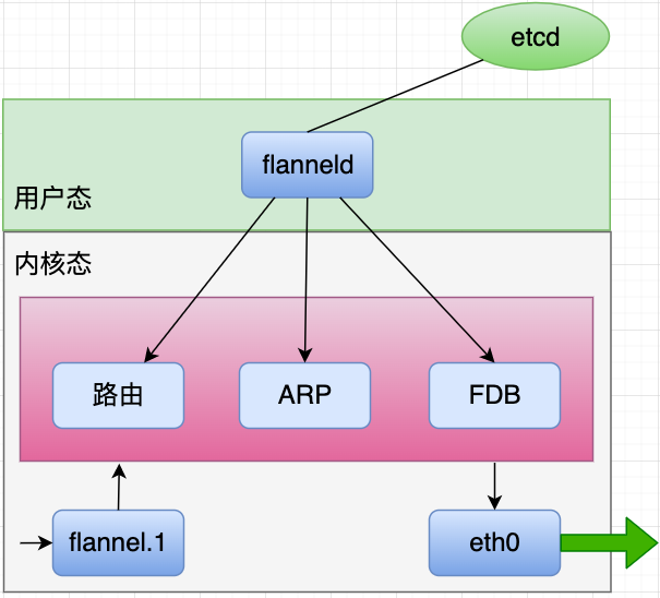
- 通过上述分析可知,在flannel vxlan模式下,集群中每增加一个节点,都需要在其它节点上增加三条数据:一个路由表项、一个ARP表项和一个FDB表项
- route表项:新增一条网关是新节点vxlan设备IP的路由
# ip route add $newNodeCidr via $newNodeVtepIP dev flannel.1
- ARP表项:新增一条新节点vxlan设备IP与MAC地址关系的ARP记录
# arp -i flannel.1 -s $newNodeVtepIP $newNodeVtepMac
- FDB表项:新增一条新节点vxlan设备MAC地址与新节点IP关系的记录
# bridge fdb append $newNodeVtepMac dev flannel.1 dst $newNodeIP
三. flanneld进程
-
flannel UDP模式下会在每个节点上有一个用户态进程flanneld,这个进程主要有两个作用
- UDP数据包的封解包
- 节点上路由表项的动态更新
-
在flannel vxlan模式下,每个节点上也会有一个用户态进程flanneld,但是此时的flanneld不再负责封解包(vxlan设备负责封解包),只负责监听节点的变化,并用程序完成前文更新本节点路由表项、ARP表项和FDB表项的命令
四. BGP
-
calico是一个网络方面的开源项目,它在kubernetes和虚拟机等场景下能提供两种能力:网络连通和网络安全策略(ACL)。calico的ACL会在后续文章中再做说明,本文只讨论calico的网络连通问题
-
针对网络连通问题,当前calico有两种比较成熟的方案:BGP模式和IPIP模式,本文只介绍calico BGP模式,IPIP模式会在下篇文章中再做说明,敬请期待。
1. host-gateway与BGP
-
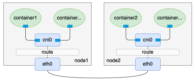
flannel通过路由方式实现的一种高性能容器跨主机通信方案: flannel host-gateway模式,这里介绍的calico BGP模式和flannel host-gateway方式非常类似,也是通过一条网关为目标宿主机IP的路由来实现的,因此calico BGP模式也要求节点间二层互通
-
flannel host-gateway模式:
- 再看看calico BGP模式
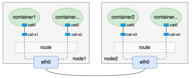
- 单纯从上面两个图来看,calico BGP模式相比于flannel host-gateway模式来说,只是少了一个cni0网桥,其它几乎都是一样的。没错,这也是前文提到这两种网络方案很类似的原因
2. 原理
-
我们一直在说BGP模式,那么到底什么是BGP呢?BGP在calico中又起到了什么作用呢?
-
BGP全称是Border Gateway Protocol,即边界网关协议,读者无需为BGP这个不太熟悉的名词担心,因为当前只需理解下述例子就可以理解BGP在calico中的作用:
假设当前有如下两台可以BGP通信的机器:
主机名 主机IP 负责容器IP段 node1 192.168.1.100 1.1.1.0/24 node2 192.168.2.100 1.1.2.0/24 则node1发送给192.168.1.100的BGP信息可以简单看作:
[BGP信息]
我负责的容器网段是1.1.1.0/24
我的主机IP是192.168.1.100
同理,node2发送给192.168.1.100的BGP信息可以简单看作:
[BGP信息]
我负责的容器网段是1.1.2.0/24
我的主机IP是192.168.2.100
- 通过BGP通信,每个节点都能知道其它节点负责的容器IP段以及对应的宿主机IP,这样我们就能配置类似flannel host-gateway模式的路由,这就是BGP在calico项目中作用的最简易理解
3. bird
- BGP是一种数据协议,发送和接收BGP类型的数据需要有客户端程序,calico使用的BGP客户端程序是bird,本文也以bird为例,来初步了解BGP。
注:我当前使用的两台示例机器是centos 7,不同系统相关命令可能存在一定的差异
- 安装bird
# yum install bird2 -y
- 启动bird
# systemctl enable bird
Created symlink from /etc/systemd/system/multi-user.target.wants/bird.service to /usr/lib/systemd/system/bird.service.
# systemctl start bird
- 验证bird是否安装成功:
# birdc show route
BIRD 2.0.9 ready.
注:
- 如果bird进程没起来,我们可以用
journalctl -u bird
查看bird的启动日志排查原因,如果bird进程起来了但是没达到我们期望的效果,我们可以用birdc show route all
和birdc show proto all
查找相关错误信息。- calico封装了calicoctl工具来查看BGP相关数据。
- 接下来我们通过实际配置bird来加深对bird的理解。我当前环境的两台机器信息如下:
| 主机名 | 主机IP | 负责容器IP段 |
|---|---|---|
| node1 | 10.0.12.11 | 1.1.1.0/24 |
| node2 | 10.0.12.7 | 1.1.2.0/24 |
- 不同主机间bird的BGP通信是通过TCP完成的,因此需要在bird的配置文件中提前配置好对方的IP和端口(也就是neighbor信息),默认端口是179。bird默认的配置文件是/etc/bird.conf,以node1为例,我们对bird的配置文件稍作修改(修改前建议先备份一下默认配置文件)
router id 10.0.12.11;

protocol static {
  ipv4;

  route 1.1.1.0/24 blackhole;
}

filter calico_kernel_programming {
  accept;
}

protocol kernel {
  learn;             # Learn all alien routes from the kernel
  persist;           # Don't remove routes on bird shutdown
  scan time 2;       # Scan kernel routing table every 2 seconds
  ipv4 {
    import all;
    export all;
  };
  graceful restart;
  merge paths on;
}

protocol device {
  debug { states };
  scan time 2;    # Scan interfaces every 2 seconds
}

protocol direct {
  debug { states };
  interface -"veth*", "*";
}

function calico_aggr ()
{
      if ( net = 1.1.1.0/24 ) then { accept; }
      if ( net ~ 1.1.1.0/24 ) then { reject; }
}

filter calico_export_to_bgp_peers {
  calico_aggr();

  if ( net ~ 1.1.0.0/16 ) then {
    accept;
  }
  reject;
}

template bgp bgp_template {
  debug { states };
  description "Connection to BGP peer";
  local 10.0.12.11 as 50011;
  ipv4 {
    import all;
    export filter calico_export_to_bgp_peers;
  };
  graceful restart;
  connect delay time 2;
  connect retry time 5;
  error wait time 5,30;
}

protocol bgp Mesh_10_0_12_7 from bgp_template {
  neighbor 10.0.12.7 port 179 as 50007;
}
-
上述配置文件简单翻译就是:我负责1.1.1.0/24网段IP,我的主机IP是10.0.12.11,我要把这条信息发给我的邻居10.0.12.7。
-
该配置文件需要注意几个地方
- route id作为每个BGP client的唯一标识,不能重复,一般以主机IP命名;
- protocol static下有一条黑洞路由,具体作用下文会说明;
- protocol direct下有条-"veth*"的条目,我在本文后续中的操作会把veth pair的名称以veth开头,因此这里是-“veth*”,calico原生的veth pair名称是以cali开头,它配置的是-“cali*”;
- function calico_aggr中配置的信息在本文中是要告知其它机器你负责的容器IP网段是什么;
- filter calico_export_to_bgp_peers中1.1.0.0/16表示容器IP大网段范围;
- template bgp bgp_template下,local $IP as $um条目中,填的是当前宿主机,num是作为信息校验的一个标识,需要在对方的配置中匹配上;
- protocol bgp Mesh_10_0_12_7 from bgp_template下,neighbor $IP $port as 条目中, I P 填的是邻居的宿主机 I P ,填写默认的的端口, n u m 则要与对方 t e m p l a t e b g p b g p t e m p l a t e 的 n u m (也就是上述第 6 点中的 条目中,IP填的是邻居的宿主机IP,填写默认的的端口,num则要与对方template bgp bgp_template的num(也就是上述第6点中的 条目中,IP填的是邻居的宿主机IP,填写默认的的端口,num则要与对方templatebgpbgpt?emplate的num(也就是上述第6点中的num)对应上。
- 参考上述node1上bird的配置文件修改好node2上bird的配置文件
router id 10.0.12.7;

protocol static {
  ipv4;

  route 1.1.2.0/24 blackhole;
}

filter calico_kernel_programming {
  accept;
}

protocol kernel {
  learn;             # Learn all alien routes from the kernel
  persist;           # Don't remove routes on bird shutdown
  scan time 2;       # Scan kernel routing table every 2 seconds
  ipv4 {
    import all;
    export all;
  };
  graceful restart;
  merge paths on;
}

protocol device {
  debug { states };
  scan time 2;    # Scan interfaces every 2 seconds
}

protocol direct {
  debug { states };
  interface -"veth*", "*"; # Exclude cali* and kube-ipvs* but
                                          # include everything else.  In
                                          # IPVS-mode, kube-proxy creates a
                                          # kube-ipvs0 interface. We exclude
                                          # kube-ipvs0 because this interface
                                          # gets an address for every in use
                                          # cluster IP. We use static routes
                                          # for when we legitimately want to
                                          # export cluster IPs.
}

function calico_aggr ()
{
      if ( net = 1.1.2.0/24 ) then { accept; }
      if ( net ~ 1.1.2.0/24 ) then { reject; }
}

filter calico_export_to_bgp_peers {
  calico_aggr();

  if ( net ~ 1.1.0.0/16 ) then {
    accept;
  }
  reject;
}

template bgp bgp_template {
  debug { states };
  description "Connection to BGP peer";
  local 10.0.12.7 as 50007;
  ipv4 {
    import all;
    export filter calico_export_to_bgp_peers;
  };
  graceful restart;
  connect delay time 2;
  connect retry time 5;
  error wait time 5,30;
}

protocol bgp Mesh_10_0_12_11 from bgp_template {
  neighbor 10.0.12.11 port 179 as 50011;
}
- 两个节点准备重启bird,重启前先看看宿主机上的路由
// node1
# route -n
Kernel IP routing table
Destination     Gateway         Genmask         Flags Metric Ref    Use Iface
0.0.0.0         10.0.12.1       0.0.0.0         UG    0      0        0 eth0
1.1.2.0         10.0.12.7       255.255.255.0   UG    0      0        0 eth0
# ip route
default via 10.0.12.1 dev eth0
10.0.12.0/22 dev eth0 proto kernel scope link src 10.0.12.11


// node2
# route -n
Kernel IP routing table
Destination     Gateway         Genmask         Flags Metric Ref    Use Iface
0.0.0.0         10.0.12.1       0.0.0.0         UG    0      0        0 eth0
10.0.12.0       0.0.0.0         255.255.252.0   U     0      0        0 eth0
# ip route
default via 10.0.12.1 dev eth0
10.0.12.0/22 dev eth0 proto kernel scope link src 10.0.12.7
- 重启bird:
// node1
# systemctl restart bird

// node2
# systemctl restart bird
- 重启完bird再看看宿主机上的路由:
// node1
# route -n
Kernel IP routing table
Destination     Gateway         Genmask         Flags Metric Ref    Use Iface
0.0.0.0         10.0.12.1       0.0.0.0         UG    0      0        0 eth0
1.1.1.0         0.0.0.0         255.255.255.0   U     32     0        0 *
1.1.2.0         10.0.12.7       255.255.255.0   UG    0      0        0 eth0
10.0.12.0       0.0.0.0         255.255.252.0   U     0      0        0 eth0
# ip route
default via 10.0.12.1 dev eth0
blackhole 1.1.1.0/24 proto bird metric 32
1.1.2.0/24 via 10.0.12.7 dev eth0
10.0.12.0/22 dev eth0 proto kernel scope link src 10.0.12.11

// node2
# route -n
Kernel IP routing table
Destination     Gateway         Genmask         Flags Metric Ref    Use Iface
0.0.0.0         10.0.12.1       0.0.0.0         UG    0      0        0 eth0
1.1.1.0         10.0.12.11      255.255.255.0   UG    0      0        0 eth0
1.1.2.0         0.0.0.0         255.255.255.0   U     32     0        0 *
10.0.12.0       0.0.0.0         255.255.252.0   U     0      0        0 eth0
# ip route
default via 10.0.12.1 dev eth0
1.1.1.0/24 via 10.0.12.11 dev eth0
blackhole 1.1.2.0/24 proto bird metric 32
10.0.12.0/22 dev eth0 proto kernel scope link src 10.0.12.7
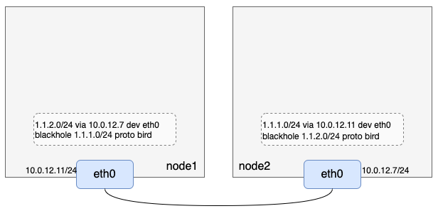
- 可以看到,bird重启后每台机器上多了两条路由,第一条是到本机负责容器IP网段的黑洞路由,这条路由下文会再说明;**第二****条是目的IP段是对方容器IP段、网关是对方宿主机IP的路由。**其中第二条路由就是通过BGP通信,接收到对方发来的BGP信息计算生成的路由,这条路由和flannel host-gateway模式生成的路由功能是一样的。
4. BGP Route Reflector
- 上文说到bird的BGP数据是通过TCP传输的,而且在配置中我们也配置了邻居的IP(即对方宿主机IP)和监听端口,细心的读者到这里可能就会发现,当前配置的bird是两两互联的,如果有N个节点,那么就会有N^2条TCP连接,当节点数达到成百上千的时候,这些连接是很难维护的。
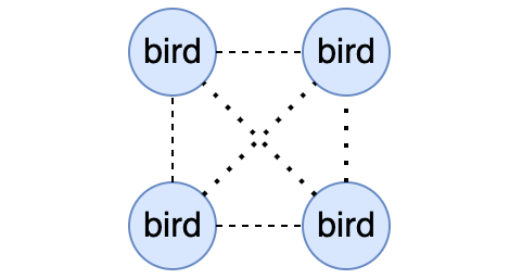
- 幸运的是,BGP支持一种叫做Route Reflector模式(俗称rr模式),这种模式下允许使用少数几个节点作为中转节点,其它节点连接上这几个中转节点即可,大大减少了节点间的TCP连接数。calico也建议如果集群中的节点数超过100时开启BGP rr模式,我们也可以分析出来BGP rr模式也仅仅是影响bird的组网,并不影响最终生成的路由配置。

五. calico BGP实现
- 通过前文配置和启动bird,我们当前有了如下环境信息:
1. 创建netns、veth pair
我们再把netns和veth pair补上,注意对比flannel网络模式是没有网桥cni0的:
// node1
// 创建网络命名空间netns1
[root@VM-12-11-centos ~]# ip netns add netns1
// 创建虚拟网络设备对veth1-veth2
[root@VM-12-11-centos ~]# ip link add veth1 type veth peer name veth2
// 把veth2放入网络命名空间netns1
[root@VM-12-11-centos ~]# ip link set veth2 netns netns1
// 给veth2配置IP并up
[root@VM-12-11-centos ~]# ip netns exec netns1 ifconfig veth2 1.1.1.2/24 up
// 设备veth1 up
[root@VM-12-11-centos ~]# ifconfig veth1 up
// 查看netns1路由
[root@VM-12-11-centos ~]# ip netns exec netns1 route -n
Kernel IP routing table
Destination     Gateway         Genmask         Flags Metric Ref    Use Iface
1.1.1.0         0.0.0.0         255.255.255.0   U     0      0        0 veth2

// node2
// 创建网络命名空间netns2
[root@VM-12-7-centos ~]# ip netns add netns2
// 创建虚拟网络设备对veth3-veth4
[root@VM-12-7-centos ~]# ip link add veth3 type veth peer name veth4
// 把veth4放入网络命名空间netns2
[root@VM-12-7-centos ~]# ip link set veth4 netns netns2
// 给veth4配置IP并up
[root@VM-12-7-centos ~]# ip netns exec netns2 ifconfig veth4 1.1.2.2/24 up
// 设置veth3 up
[root@VM-12-7-centos ~]# ifconfig veth3 up
// 查看netns2路由
[root@VM-12-7-centos ~]# ip netns exec netns2 route -n
Kernel IP routing table
Destination     Gateway         Genmask         Flags Metric Ref    Use Iface
1.1.2.0         0.0.0.0         255.255.255.0   U     0      0        0 veth4
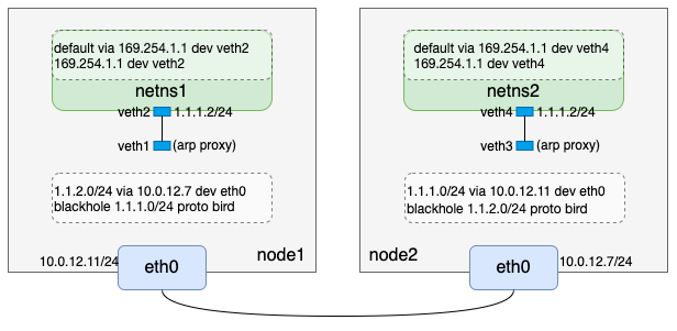
到这里我们完成了如下逻辑:
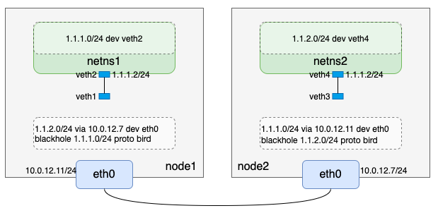
我们注意到两点:
- node1上的veth1和node2上的veth3,只是up状态但是并没有配置IP;
- node1上netns1网络命名空间只有目的网段是1.1.1.0/24的路由,node2上netns2网络命名空间只有目的网段是1.1.2.0/24的路由。
通过上述环境准备,我们发现创建的网络命名空间内无法访问非本宿主机维护外的容器网段IP,例如node1上netns1无法访问1.1.2.0/24,因为该网络命名空间内没有对应的路由。回忆下flannel host-gateway模式,我们是在该网络命名空间下加了一条网关是网桥cni0的默认路由,但是calico没有cni0网桥,该如何处理呢?这里calico用到了一点点“黑科技”——arp proxy。
arp proxy
calico为了简化网络配置,会在容器网络命名空间内添加一条网关是169.254.1.1(预留的本地网段IP,实际中并不存在某个网络设备IP是它)的默认路由,这样将容器内的默认路由都设置成了一样,不需要动态更新。即容器网络命名空间下路由为:
# ip route
default via 169.254.1.1 dev eth0
169.254.1.1 dev eth0
注:为了和之前的文章保持一致,本文手动创建的网络命名空间内的网卡还是延续之前veth开头的命名规则,没有改为eth0。
以node1为例,在netns1网络命名空间内添加了网关是169.254.1.1的默认路由后,容器会查询下一跳(即169.254.1.1)的MAC地址,这个ARP请求从netns1网络命名空间内通过veth2到达宿主机上veth pair的另一端veth1。veth1只有MAC地址没有IP,收到这个ARP请求后会怎么处理呢?答案是veth1直接应答,返回自己的MAC地址,后续netns1网络命名空间报文IP还是目的IP,但是MAC地址都变成了主机上veth1的MAC地址,也就是netns1上出来的报文都会发给主机网络,主机再根据目的IP地址进行转发。
veth1不管ARP请求内容直接返回自己MAC地址做应答的行为称为“ARP proxy”,可通过把 /proc/sys/net/ipv4/conf/veth1/proxy_arp 置一来开启该功能。
2. 重新配置出方向路由
通过arp proxy知识的补充,我们在node1和node2上执行如下命令重新配置出方向路由:
// node1
// netns1网络命名空间内先删除配置IP时自动生成的路由
[root@VM-12-11-centos ~]# ip netns exec netns1 ip route del 1.1.1.0/24
// 宿主机上开启veth1的arp proxy
[root@VM-12-11-centos ~]# echo 1 > /proc/sys/net/ipv4/conf/veth1/proxy_arp
// netns1网络命名空间内添加169.254.1.1路由
[root@VM-12-11-centos ~]# ip netns exec netns1 ip route add 169.254.1.1 dev veth2
// netns1网络命名空间内添加默认路由
[root@VM-12-11-centos ~]# ip netns exec netns1 ip route add default via 169.254.1.1 dev veth2
// 查看netns1网络命名空间路由
[root@VM-12-11-centos ~]# ip netns exec netns1 ip route
default via 169.254.1.1 dev veth2
169.254.1.1 dev veth2 scope link


// node2
// netns2网络命名空间内先删除配置IP时自动生成的路由
[root@VM-12-7-centos ~]# ip netns exec netns2 ip route del 1.1.2.0/24
// 宿主机上开启veth3的arp proxy
[root@VM-12-7-centos ~]# echo 1 > /proc/sys/net/ipv4/conf/veth3/proxy_arp
// netns2网络命名空间内添加169.254.1.1路由
[root@VM-12-7-centos ~]# ip netns exec netns2 ip route add 169.254.1.1 dev veth4
// netns2网络命名空间内添加默认路由
[root@VM-12-7-centos ~]# ip netns exec netns2 ip route add default via 169.254.1.1 dev veth4
// 查看netns2网络命名空间路由
[root@VM-12-7-centos ~]# ip netns exec netns2 ip route
default via 169.254.1.1 dev veth4
169.254.1.1 dev veth4 scope link
到这里,我们完成了如下逻辑:
3. 配置入方向路由
通过上述配置,数据包从自建网络命名空间出来是没问题了,但是从宿主机默认网络命名空间到自建网络命名空间回程数据包呢?calico也是采用配置一条路由来实现的。以node1上的netns1网络命名空间为例,会配置一条如下路由:
[root@VM-12-11-centos ~]# ip route add 1.1.1.2/32 dev veth1
同理node2上也会配置一条:
[root@VM-12-7-centos ~]# ip route add 1.1.2.2/32 dev veth3
所以,到这里我们完成了如下逻辑:
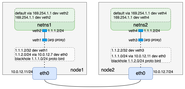
当前我们只是以一个网络命名空间为例,假设节点上有N个网络命名空间,那么calico就会在节点上就会配置N条入方向的路由。
4. 黑洞路由
[root@VM-12-11-centos ~]# route -n | grep 1.1.1
1.1.1.0         0.0.0.0         255.255.255.0   U     32     0        0 *
1.1.1.2         0.0.0.0         255.255.255.255 UH    0      0        0 veth1
[root@VM-12-11-centos ~]# ip route | grep 1.1.1
blackhole 1.1.1.0/24 proto bird metric 32
1.1.1.2 dev veth1 scope link
前文提到,calico的bird会配置一条黑洞路由,例如node1上会有一条1.1.1.0/24 blackhole的黑洞路由,结合入方向的路由(1.1.1.2/32 dev veth1)和路由的最长匹配原则,此时如果有大量请求访问1.1.1.0/24下的不存在的IP(非1.1.1.2)时,会路由到黑洞路由,这样能有效减小这些无效请求对系统负载的影响。
5. 验证
我们通过前面的操作从理论上实现了两个二层互通节点间的容器网络通信,我们来验证一下跨节点自建网络命名空间通信:
// node1
[root@VM-12-11-centos ~]# ip netns exec netns1 ping -c 1 1.1.2.2
PING 1.1.2.2 (1.1.2.2) 56(84) bytes of data.
64 bytes from 1.1.2.2: icmp_seq=1 ttl=64 time=0.049 ms

--- 1.1.2.2 ping statistics ---
1 packets transmitted, 1 received, 0% packet loss, time 0ms
rtt min/avg/max/mdev = 0.049/0.049/0.049/0.000 ms

// node2
[root@VM-12-7-centos ~]# ip netns exec netns2 ping -c 1 1.1.1.2
PING 1.1.1.2 (1.1.1.2) 56(84) bytes of data.
64 bytes from 1.1.1.2: icmp_seq=1 ttl=64 time=0.019 ms

--- 1.1.2.2 ping statistics ---
1 packets transmitted, 1 received, 0% packet loss, time 0ms
rtt min/avg/max/mdev = 0.019/0.019/0.019/0.000 ms
6. 分析
- 理论加实践验证后,我们以1.1.1.2 ping 1.1.2.2为例,重新梳理下从node1上网络命名空间netns1到node2上网络命名空间netns2的报文传输过程:
- 数据包在node1上netns1网络协议栈组装好,通过匹配默认路由default via 169.254.1.1 dev veth2,数据包从veth2发出;
- node1上从veth2出去的数据包到达veth pair的另一端veth1;
- 数据包匹配bird生成的1.1.2.0/24 via 10.0.12.7 dev eth0路由,把数据包从eth0发出,到达下一跳10.0.12.7,也就是node2;
- node2上匹配路由1.1.2.2/32 dev veth3,数据包发往veth3;
- node2上从veth3过来的数据包到达veth pair的另一端,netns2网络命名空间下的veth4;
- node2上netns2网络命名空间下的veth4发现1.1.2.2是自己,构造回程报文,从veth4发出;
- node2上veth4发出来的报文到达veth pair的另一端veth3;
- node2上到达veth3的报文匹配路由1.1.1.0/24 via 10.0.12.11/32 dev eth0,从eth0发出到达node1;
- node1上匹配1.1.1.2/32 dev veth1到达veth pair的一端veth1;
- node1上从veth1过来的包到达veth pair的另一端,即netns1网络命名空间下的veth2;
- node1上netns1网络命名空间下的veth2收到回程报文。
7. calico BGP结论
-
通过前面的步骤,我们调通了两个节点间的跨主机网络通信模型,但是与calico项目本身的结合还不是很密切,例如bird的配置怎么维护?入方向路由谁来配置?,我们再从这一角度分析下calico BGP模式。
-
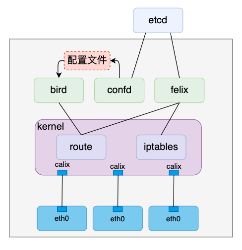
安装完calico之后会创建一个叫作calico-node的daemonSet,daemonSet的特性是会在每个节点上起个pod,这个pod主要有两个功能:
- 通过initContainer安装calico相关组件,如calico cni等插件
- 通过普通容器启动三个进程:bird、confd和felix
我们主要关注第二点的三个进程在本文中的作用
- bird
bird在前文中已经提到,主要是通过BGP通信,实现以下三个功能:
- 生成一条黑洞路由;
- 把本机上的负责的容器网段和主机IP“广播”出去;
- 接收其它bird发过来的网段和主机IP信息,在本地生成路由。
- confd
前文我们操作bird时,配置文件都是手动维护的,其中配置项包含的关键信息有本机负责的容器网段、本机IP、邻居节点IP等,如果考虑kubernetes的增加/移除节点等场景,手动维护这些配置的成本太高了,作为一个成熟的网络方案,calico肯定也不会通过手动维护的方式来配置bird。
confd就是负责自动维护bird配置的进程,它通过直接或间接监听ectd中相应信息变化,更新bird配置文件,之后通过reload操作使bird新的配置生效。
- felix
felix进程在本文中主要是负责容器网络命名空间入方向的的路由维护,例如node1上的1.1.1.2/32 dev veth1。另外,文章开头提到的ACL功能,也是felix通过维护iptables规则来实现的。
- calico BGP通信是基于TCP协议的,所以只要节点间三层互通即可完成,即三层互通的环境bird就能生成与邻居有关的路由。但是这些路由和flannel host-gateway模式一样,需要二层互通才能访问的通,因此如果在实际环境中配置了BGP模式生成了路由但是不同节点间pod访问不通,可能需要再确认下节点间是否二层互通
六. IPIP
-
calico IPIP模式是calico默认模式
-
calico BGP模式的原理与实现,并强调了BGP模式要求节点间二层互通, calico BGP模式原理
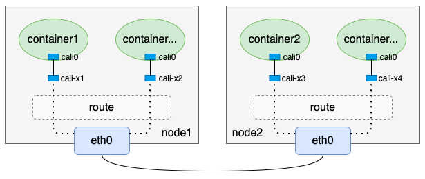
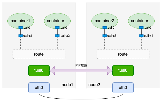
- 为了解决某些三层互通、但二层不互通的场景,calico实现了IPIP模式,IPIP模式原理如下
1. tunl0设备
- calico IPIP模式中的tunl0是一个ipip隧道(tunnel),flannel UDP模式使用了一个叫作flannel0的tun设备, calico的tunl0隧道底层是基于tun设备实现的,可以看做是tun设备的高级应用
calico使用的是ipip隧道,因此本文仅介绍ipip隧道,其它类型的隧道读者可查看相关资料进行了解
2. IPIP隧道
- 要使用ipip隧道,需要内核加载ipip.ko模块,可以用lsmod命令查看当前是否已加载ipip模块:
# lsmod | grep ipip
#
- 如果没有加载ipip模块,可用modprobe命令加载
# modprobe ipip
# lsmod | grep ipip
ipip                   13465  0
tunnel4                13252  1 ipip
ip_tunnel              25163  1 ipip
- 内核加载ipip模块后,机器上所有的网络命名空间都会自动出现一个tunl0设备,这个设备就是ipip隧道设备。
When the ipip module is loaded, or an IPIP device is created for the first time, the Linux kernel will create a tunl0 default device in each namespace, with attributes local=any and remote=any. When receiving IPIP protocol packets, the kernel will forward them to tunl0 as a fallback device if it can’t find another device whose local/remote attributes match their source or destination address more closely.
- 我们可以用如下命令查看ipip隧道设备:
# ip -d link show tunl0
35: tunl0@NONE: <NOARP> mtu 1480 qdisc noop state DOWN mode DEFAULT group default qlen 1000
    link/ipip 0.0.0.0 brd 0.0.0.0 promiscuity 0
    ipip remote any local any ttl inherit nopmtudisc numtxqueues 1 numrxqueues 1 gso_max_size 65536 gso_max_segs 65535

# ip netns exec netns1 ip -d link show tunl0
2: tunl0@NONE: <NOARP> mtu 1480 qdisc noop state DOWN mode DEFAULT group default qlen 1000
    link/ipip 0.0.0.0 brd 0.0.0.0 promiscuity 0
    ipip remote any local any ttl inherit nopmtudisc numtxqueues 1 numrxqueues 1 gso_max_size 65536 gso_max_segs 65535
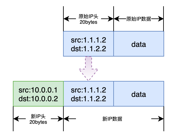
- ipip隧道的原理是在IPv4的基础上封装一个IPv4报文,那么就会有如下报文格式。我们可以看到封装后的IP报文比原始的IP报文多了一个IP头,而IP头长度为20字节,因此为了防止经过tunl0后的数据包在其它网络设备传输时超过网络设备MTU而被丢弃,ipip隧道设备默认的MTU会比一般网络设备的默认的MTU小20。一般网络设备的MTU默认为1500,所以ipip隧道设备默认MTU为1500-20=1480。
(一). calico IPIP模式的实现
- 有了以上知识准备,我们来一步一步实现calico IPIP模式。
1. 准备宿主机
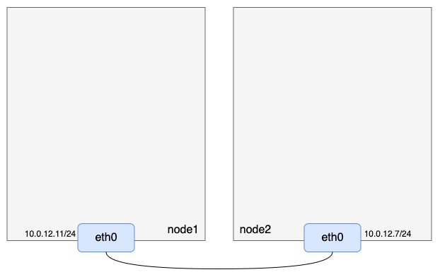
准备两台三层互通的机器,注意开启ip_forward转发,且node1负责的容器IP网段为1.1.1.0/24,node2负责的容器IP网段为1.1.2.0/24:
2. 准备ipip隧道设备
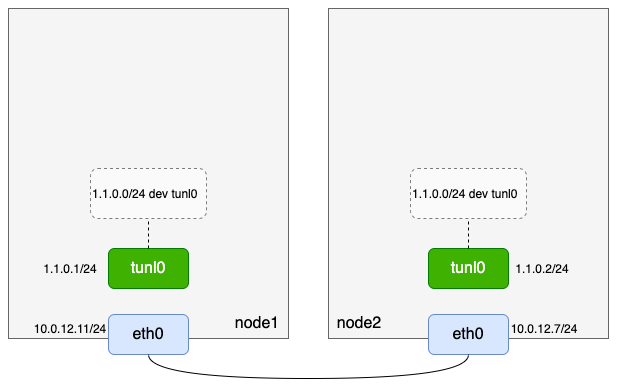
两台机器均加载ipip模块,给ipip隧道设备tunl0配置ip并up
// node1
// 加载ipip模块
[root@VM-12-11-centos ~]# modprobe ipip
// 验证模块是否加载成功
[root@VM-12-11-centos ~]# lsmod | grep ipip
ipip                   13465  0
tunnel4                13252  1 ipip
ip_tunnel              25163  1 ipip
// 查看ipip隧道设备
[root@VM-12-11-centos ~]# ip -d link show tunl0
35: tunl0@NONE: <NOARP> mtu 1480 qdisc noop state DOWN mode DEFAULT group default qlen 1000
    link/ipip 0.0.0.0 brd 0.0.0.0 promiscuity 0
    ipip remote any local any ttl inherit nopmtudisc numtxqueues 1 numrxqueues 1 gso_max_size 65536 gso_max_segs 65535
// 给ipip隧道设备配置IP并up
[root@VM-12-11-centos ~]# ifconfig tunl0 1.1.0.1/24 up
// 查看ipip隧道设备ip信息
[root@VM-12-11-centos ~]# ifconfig tunl0
tunl0: flags=193<UP,RUNNING,NOARP>  mtu 1480
        inet 1.1.0.1  netmask 255.255.255.0
        tunnel   txqueuelen 1000  (IPIP Tunnel)
        RX packets 0  bytes 0 (0.0 B)
        RX errors 0  dropped 0  overruns 0  frame 0
        TX packets 0  bytes 0 (0.0 B)
        TX errors 0  dropped 0 overruns 0  carrier 0  collisions 0
// 查看路由
[root@VM-12-11-centos ~]# route -n
Kernel IP routing table
Destination     Gateway         Genmask         Flags Metric Ref    Use Iface
0.0.0.0         10.0.12.1       0.0.0.0         UG    0      0        0 eth0
1.1.0.0         0.0.0.0         255.255.255.0   U     0      0        0 tunl0
10.0.12.0       0.0.0.0         255.255.252.0   U     0      0        0 eth0


// node2
[root@VM-12-7-centos ~]# modprobe ipip
[root@VM-12-7-centos ~]# lsmod | grep ipip
ipip                   13465  0
tunnel4                13252  1 ipip
ip_tunnel              25163  1 ipip
[root@VM-12-7-centos ~]# ip -d link show tunl0
9: tunl0@NONE: <NOARP> mtu 1480 qdisc noop state DOWN mode DEFAULT group default qlen 1000
    link/ipip 0.0.0.0 brd 0.0.0.0 promiscuity 0
    ipip remote any local any ttl inherit nopmtudisc numtxqueues 1 numrxqueues 1 gso_max_size 65536 gso_max_segs 65535
[root@VM-12-7-centos ~]# ifconfig tunl0 1.1.0.2/24 up
[root@VM-12-7-centos ~]# ifconfig tunl0
tunl0: flags=193<UP,RUNNING,NOARP>  mtu 1480
        inet 1.1.0.2  netmask 255.255.255.0
        tunnel   txqueuelen 1000  (IPIP Tunnel)
        RX packets 0  bytes 0 (0.0 B)
        RX errors 0  dropped 0  overruns 0  frame 0
        TX packets 0  bytes 0 (0.0 B)
        TX errors 0  dropped 0 overruns 0  carrier 0  collisions 0
[root@VM-12-7-centos ~]# route -n
Kernel IP routing table
Destination     Gateway         Genmask         Flags Metric Ref    Use Iface
0.0.0.0         10.0.12.1       0.0.0.0         UG    0      0        0 eth0
1.1.0.0         0.0.0.0         255.255.255.0   U     0      0        0 tunl0
10.0.12.0       0.0.0.0         255.255.252.0   U     0      0        0 eth0
到这里,我们准备的逻辑如下:
3. 准备机器隧道路由
-
前文有提到:
When receiving IPIP protocol packets, the kernel will forward them to tunl0 as a fallback device if it can't find another device whose local/remote attributes match their source or destination address more closely,以node1为例,我们基于tunl0设备的相关特点,可以增加一条路由1.1.2.0/24 via 10.0.12.7 dev tunl0。 -
然而如果直接执行
ip route add 1.1.2.0/24 via 10.0.12.7 dev tunl0,你会发现会报如下错误:
[root@VM-12-11-centos ~]# ip route add 1.1.2.0/24 via 10.0.12.7 dev tunl0
RTNETLINK answers: Network is unreachable
- 那是因为tunl0(1.1.0.1)无法与网关10.0.12.7直接通信,但是可以通过增加一个onlink选项使得这条路由可以正常配置。
参考(需要能访问外网):https://medium.com/@samueldarwin/full-mesh-ipip-tunnels-d16888913e40
# ip route add 1.1.2.0/24 via 10.0.12.7 dev tunl0 onlink
- 匹配到这条路由的数据包最终会从物理网卡eth0出去,此时eth0的IP也就是ipip隧道的外层local IP,而这条路由的网关(via后的IP)就是ipip隧道的外层remote IP,内层local IP和内层remote IP还是原始源IP和目的IP。于是node1和node2上有如下操作:
// node1
[root@VM-12-11-centos ~]# ip route add 1.1.2.0/24 via 10.0.12.7 dev tunl0 onlink
[root@VM-12-11-centos ~]# route -n
Kernel IP routing table
Destination     Gateway         Genmask         Flags Metric Ref    Use Iface
0.0.0.0         10.0.12.1       0.0.0.0         UG    0      0        0 eth0
1.1.0.0         0.0.0.0         255.255.255.0   U     0      0        0 tunl0
1.1.2.0         10.0.12.7       255.255.255.0   UG    0      0        0 tunl0
10.0.12.0       0.0.0.0         255.255.252.0   U     0      0        0 eth0

// node2
[root@VM-12-7-centos ~]# ip route add 1.1.1.0/24 via 10.0.12.11 dev tunl0 onlink
[root@VM-12-7-centos ~]# route -n
Kernel IP routing table
Destination     Gateway         Genmask         Flags Metric Ref    Use Iface
0.0.0.0         10.0.12.1       0.0.0.0         UG    0      0        0 eth0
1.1.0.0         0.0.0.0         255.255.255.0   U     0      0        0 tunl0
1.1.1.0         10.0.12.11      255.255.255.0   UG    0      0        0 tunl0
10.0.12.0       0.0.0.0         255.255.252.0   U     0      0        0 eth0
- 为了后面更加简洁明了,我们把tunl0设备那条默认添加的路由删除:
// node1
[root@VM-12-11-centos ~]# ip route delete 1.1.0.0/24
[root@VM-12-11-centos ~]# route -n
Kernel IP routing table
Destination     Gateway         Genmask         Flags Metric Ref    Use Iface
0.0.0.0         10.0.12.1       0.0.0.0         UG    0      0        0 eth0
1.1.2.0         10.0.12.7       255.255.255.0   UG    0      0        0 tunl0
10.0.12.0       0.0.0.0         255.255.252.0   U     0      0        0 eth0

// node2
[root@VM-12-7-centos ~]# ip route delete 1.1.0.0/24
[root@VM-12-7-centos ~]# route -n
Kernel IP routing table
Destination     Gateway         Genmask         Flags Metric Ref    Use Iface
0.0.0.0         10.0.12.1       0.0.0.0         UG    0      0        0 eth0
1.1.1.0         10.0.12.11      255.255.255.0   UG    0      0        0 tunl0
10.0.12.0       0.0.0.0         255.255.252.0   U     0      0        0 eth0
- 到这里,我们完成了如下模型:
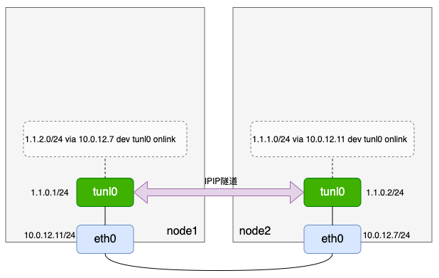
在calico项目中,这条与对应节点“建立ipip隧道的路由”是由bird生成的,本文侧重calico IPIP模式原理,bird生成路由以及bird配置文件相关语法资料。
3. 准备netns、veth pair
calico IPIP模式和calico BGP模式一样,也是没有网桥去汇总宿主机默认网络命名空间的veth pair
// node1
// 创建网络命名空间netns1
[root@VM-12-11-centos ~]# ip netns add netns1
// 创建虚拟网络设备对veth1-veth2
[root@VM-12-11-centos ~]# ip link add veth1 type veth peer name veth2
// 把veth2放入网络命名空间netns1
[root@VM-12-11-centos ~]# ip link set veth2 netns netns1
// 给veth2配置IP并up
[root@VM-12-11-centos ~]# ip netns exec netns1 ifconfig veth2 1.1.1.2/24 up
// 设备veth1 up
[root@VM-12-11-centos ~]# ifconfig veth1 up
// 查看netns1路由
[root@VM-12-11-centos ~]# ip netns exec netns1 route -n
Kernel IP routing table
Destination     Gateway         Genmask         Flags Metric Ref    Use Iface
1.1.1.0         0.0.0.0         255.255.255.0   U     0      0        0 veth2

// node2
// 创建网络命名空间netns2
[root@VM-12-7-centos ~]# ip netns add netns2
// 创建虚拟网络设备对veth3-veth4
[root@VM-12-7-centos ~]# ip link add veth3 type veth peer name veth4
// 把veth4放入网络命名空间netns2
[root@VM-12-7-centos ~]# ip link set veth4 netns netns2
// 给veth4配置IP并up
[root@VM-12-7-centos ~]# ip netns exec netns2 ifconfig veth4 1.1.2.2/24 up
// 设置veth3 up
[root@VM-12-7-centos ~]# ifconfig veth3 up
// 查看netns2路由
[root@VM-12-7-centos ~]# ip netns exec netns2 route -n
Kernel IP routing table
Destination     Gateway         Genmask         Flags Metric Ref    Use Iface
1.1.2.0         0.0.0.0         255.255.255.0   U     0      0        0 veth4
- 注意veth1和veth3的arp proxy以及网络命名空间内的路由:
// netns1网络命名空间内先删除配置IP时自动生成的路由
[root@VM-12-11-centos ~]# ip netns exec netns1 ip route del 1.1.1.0/24
// 宿主机上开启veth1的arp proxy
[root@VM-12-11-centos ~]# echo 1 > /proc/sys/net/ipv4/conf/veth1/proxy_arp
// netns1网络命名空间内添加169.254.1.1路由
[root@VM-12-11-centos ~]# ip netns exec netns1 ip route add 169.254.1.1 dev veth2
// netns1网络命名空间内添加默认路由
[root@VM-12-11-centos ~]# ip netns exec netns1 ip route add default via 169.254.1.1 dev veth2
// 查看netns1网络命名空间路由
[root@VM-12-11-centos ~]# ip netns exec netns1 ip route
default via 169.254.1.1 dev veth2
169.254.1.1 dev veth2 scope link

// node2
// netns2网络命名空间内先删除配置IP时自动生成的路由
[root@VM-12-7-centos ~]# ip netns exec netns2 ip route del 1.1.2.0/24
// 宿主机上开启veth3的arp proxy
[root@VM-12-7-centos ~]# echo 1 > /proc/sys/net/ipv4/conf/veth3/proxy_arp
// netns2网络命名空间内添加169.254.1.1路由
[root@VM-12-7-centos ~]# ip netns exec netns2 ip route add 169.254.1.1 dev veth4
// netns2网络命名空间内添加默认路由
[root@VM-12-7-centos ~]# ip netns exec netns2 ip route add default via 169.254.1.1 dev veth4
// 查看netns2网络命名空间路由
[root@VM-12-7-centos ~]# ip netns exec netns2 ip route
default via 169.254.1.1 dev veth4
169.254.1.1 dev veth4 scope link
- 同样在宿主机上添加入方向路由:
// node1
[root@VM-12-11-centos ~]# ip route add 1.1.1.2/32 dev veth1

// node2
[root@VM-12-7-centos ~]# ip route add 1.1.2.2/32 dev veth3
- 到这里我们完成了calico IPIP模式的整条链路配置:
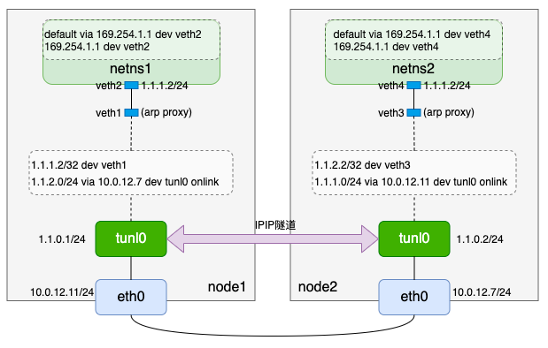
(二). 网络验证
- 我们从node1上的netns1和node2上的netns2互ping,来验证网络连通性
// node1
[root@VM-12-11-centos ~]# ip netns exec netns1 ping -c 1 1.1.2.2
PING 1.1.2.2 (1.1.2.2) 56(84) bytes of data.
64 bytes from 1.1.2.2: icmp_seq=1 ttl=62 time=0.274 ms

--- 1.1.2.2 ping statistics ---
1 packets transmitted, 1 received, 0% packet loss, time 0ms
rtt min/avg/max/mdev = 0.274/0.274/0.274/0.000 ms


// node2
[root@VM-12-7-centos ~]# ip netns exec netns2 ping -c 1 1.1.1.2
PING 1.1.1.2 (1.1.1.2) 56(84) bytes of data.
64 bytes from 1.1.1.2: icmp_seq=1 ttl=62 time=0.279 ms

--- 1.1.1.2 ping statistics ---
1 packets transmitted, 1 received, 0% packet loss, time 0ms
rtt min/avg/max/mdev = 0.279/0.279/0.279/0.000 ms
- 在node1和node2上的物理网卡eth0抓包,能看到ipip封包报文:
// node1
[root@VM-12-11-centos ~]# tcpdump -i eth0 -n host 10.0.12.7
tcpdump: verbose output suppressed, use -v or -vv for full protocol decode
listening on eth0, link-type EN10MB (Ethernet), capture size 262144 bytes
20:59:47.220363 IP 10.0.12.11 > 10.0.12.7: IP 1.1.1.2 > 1.1.2.2: ICMP echo request, id 17681, seq 1, length 64 (ipip-proto-4)
20:59:47.220546 IP 10.0.12.7 > 10.0.12.11: IP 1.1.2.2 > 1.1.1.2: ICMP echo reply, id 17681, seq 1, length 64 (ipip-proto-4)

// node2
[root@VM-12-7-centos ~]# tcpdump -i eth0 -n host 10.0.12.11
tcpdump: verbose output suppressed, use -v or -vv for full protocol decode
listening on eth0, link-type EN10MB (Ethernet), capture size 262144 bytes
20:59:47.219832 IP 10.0.12.11 > 10.0.12.7: IP 1.1.1.2 > 1.1.2.2: ICMP echo request, id 17681, seq 1, length 64 (ipip-proto-4)
20:59:47.219879 IP 10.0.12.7 > 10.0.12.11: IP 1.1.2.2 > 1.1.1.2: ICMP echo reply, id 17681, seq 1, length 64 (ipip-proto-4)
Note:
如果是云服务器,到这里可能不通。以腾讯云为例,ipip隧道协议不在默认的防火墙范围内,需要放通这两台机器间的防火墙才能正常访问。
1. cross-subnet
-
在ipip模式下,calico支持一种叫做cross-subnet的配置,所谓的cross-subnet,其实就是calico通过某种方法判断出两个节点是否是二层互通,如果是二层互通,则bird发布的规则是BGP模式的路由(类似
$cidr via $dstHost dev eth0);如果非二层互通,则配置成ipip模式路由(类似$cidr via $dstHost dev tunl0 onlink) -
其实flannel也支持“cross-subnet”功能,只不过在flannel中不叫cross-subnet而是叫作direct-routing,这两者原理都差不多:flannel vxlan模式下如果配置了direct-routing,二层互通的机器间路由类似host-gateway模式,三层互通的机器则是正常的vxlan模式路由。flannel判断是否是direct-routing的源代码如下:
// flannel/pkg/ip/iface.go
func DirectRouting(ip net.IP) (bool, error) {
    routes, err := netlink.RouteGet(ip)
    if err != nil {
        return false, fmt.Errorf("couldn't lookup route to %v: %v", ip, err)
    }
    if len(routes) == 1 && routes[0].Gw == nil {
        // There is only a single route and there's no gateway (i.e. it's directly connected)
        return true, nil
    }
    return false, nil
}
(三). flannel 与 calico支持的网络
- 我们先后介绍了flannel UDP模式(弃用)、flannel vxlan模式、flannel host-gateway模式、calico BGP模式和calico IPIP模式,其中calico BGP模式和flannel host-gateway模式原理很类似。如果查看flannel和calico最新代码,我们会发现flannel也支持IPIP模式,而calico也支持vxlan模式,也就是flannel和calico从网络方案上来看基本拉齐了。为了更加直观地对比,整理了下表格
| 模式 | flannel | calico |
|---|---|---|
| UDP模式 | 支持(但已弃用) | 不支持 |
| vxlan模式 | 支持 | 支持 |
| host-gateway模式 | 支持 | 支持(即BGP模式) |
| IPIP模式 | 支持 | 支持 |
本文来自互联网用户投稿,该文观点仅代表作者本人,不代表本站立场。本站仅提供信息存储空间服务,不拥有所有权,不承担相关法律责任。 如若内容造成侵权/违法违规/事实不符,请联系我的编程经验分享网邮箱:veading@qq.com进行投诉反馈,一经查实,立即删除!