ROS2+URDF
Building a visual robot model?
Goal:?Learn how to build a visual model of a robot that you can view in Rviz
Tutorial level:?Intermediate
Time:?20 minutes
Contents
Note
This tutorial assumes you know how to write well-formatted XML code
In this tutorial, we’re going to build a visual model of a robot that vaguely looks like R2D2. In later tutorials, you’ll learn how to?articulate the model,?add in some physical properties, and?generate neater code with xacro, but for now, we’re going to focus on getting the visual geometry correct.
Before continuing, make sure you have the?joint_state_publisher?package installed. If you installed?urdf_tutorial?binaries, this should already be the case. If not, please update your installation to include that package (use?rosdep?to check).
All of the robot models mentioned in this tutorial (and the source files) can be found in the?urdf_tutorial?package.
One Shape?
First, we’re just going to explore one simple shape. Here’s about as simple as a urdf as you can make.?[Source: 01-myfirst.urdf]
<?xml version="1.0"?>
<robot name="myfirst">
  <link name="base_link">
    <visual>
      <geometry>
        <cylinder length="0.6" radius="0.2"/>
      </geometry>
    </visual>
  </link>
</robot>

To translate the XML into English, this is a robot with the name?myfirst, that contains only one link (a.k.a. part), whose visual component is just a cylinder 0.6 meters long with a 0.2 meter radius. This may seem like a lot of enclosing tags for a simple “hello world” type example, but it will get more complicated, trust me.
To examine the model, launch the?display.launch.py?file:
ros2 launch urdf_tutorial display.launch.py model:=urdf/01-myfirst.urdf

This does three things:
Loads the specified model and saves it as a parameter for the?
robot_state_publisher?node.Runs nodes to publish?sensor_msgs/msg/JointState?and transforms (more on these later)
Starts Rviz with a configuration file
After launching?display.launch.py, you should end up with RViz showing you the following:

Things to note:
-
The fixed frame is the transform frame where the center of the grid is located. Here, it’s a frame defined by our one link, base_link.
-
The visual element (the cylinder) has its origin at the center of its geometry as a default. Hence, half the cylinder is below the grid.
Multiple Shapes?
Now let’s look at how to add multiple shapes/links. If we just add more link elements to the urdf, the parser won’t know where to put them. So, we have to add joints. Joint elements can refer to both flexible and inflexible joints. We’ll start with inflexible, or fixed joints.?[Source: 02-multipleshapes.urdf]
<?xml version="1.0"?>
<robot name="multipleshapes">
  <link name="base_link">
    <visual>
      <geometry>
        <cylinder length="0.6" radius="0.2"/>
      </geometry>
    </visual>
  </link>

  <link name="right_leg">
    <visual>
      <geometry>
        <box size="0.6 0.1 0.2"/>
      </geometry>
    </visual>
  </link>

  <joint name="base_to_right_leg" type="fixed">
    <parent link="base_link"/>
    <child link="right_leg"/>
  </joint>

</robot>

-
Note how we defined a 0.6m x 0.1m x 0.2m box
-
The joint is defined in terms of a parent and a child. URDF is ultimately a tree structure with one root link. This means that the leg’s position is dependent on the base_link’s position.
ros2 launch urdf_tutorial display.launch.py model:=urdf/02-multipleshapes.urdf

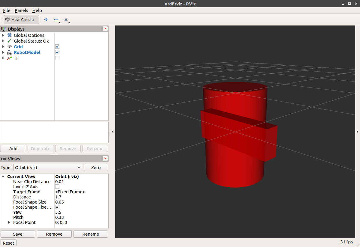
Both of the shapes overlap with each other, because they share the same origin. If we want them not to overlap we must define more origins.
Origins?
R2D2’s leg attaches to the top half of his torso, on the side. So that’s where we specify the origin of the JOINT to be. Also, it doesn’t attach to the middle of the leg, it attaches to the upper part, so we must offset the origin for the leg as well. We also rotate the leg so it is upright.?[Source: 03-origins.urdf]
<?xml version="1.0"?>
<robot name="origins">
  <link name="base_link">
    <visual>
      <geometry>
        <cylinder length="0.6" radius="0.2"/>
      </geometry>
    </visual>
  </link>

  <link name="right_leg">
    <visual>
      <geometry>
        <box size="0.6 0.1 0.2"/>
      </geometry>
      <origin rpy="0 1.57075 0" xyz="0 0 -0.3"/>
    </visual>
  </link>

  <joint name="base_to_right_leg" type="fixed">
    <parent link="base_link"/>
    <child link="right_leg"/>
    <origin xyz="0 -0.22 0.25"/>
  </joint>

</robot>

-
Let’s start by examining the joint’s origin. It is defined in terms of the parent’s reference frame. So we are -0.22 meters in the y direction (to our left, but to the right relative to the axes) and 0.25 meters in the z direction (up). This means that the origin for the child link will be up and to the right, regardless of the child link’s visual origin tag. Since we didn’t specify a rpy (roll pitch yaw) attribute, the child frame will be default have the same orientation as the parent frame.
-
Now, looking at the leg’s visual origin, it has both a xyz and rpy offset. This defines where the center of the visual element should be, relative to its origin. Since we want the leg to attach at the top, we offset the origin down by setting the z offset to be -0.3 meters. And since we want the long part of the leg to be parallel to the z axis, we rotate the visual part PI/2 around the Y axis.
ros2 launch urdf_tutorial display.launch.py model:=urdf/03-origins.urdf

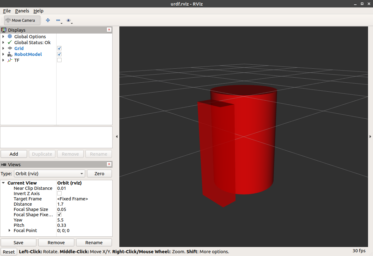
-
The launch file runs packages that will create TF frames for each link in your model based on your URDF. Rviz uses this information to figure out where to display each shape.
-
If a TF frame does not exist for a given URDF link, then it will be placed at the origin in white (ref.?related question).
Material Girl?
“Alright,” I hear you say. “That’s very cute, but not everyone owns a B21. My robot and R2D2 are not red!” That’s a good point. Let’s take a look at the material tag.?[Source: 04-materials.urdf]
<?xml version="1.0"?>
<robot name="materials">

  <material name="blue">
    <color rgba="0 0 0.8 1"/>
  </material>

  <material name="white">
    <color rgba="1 1 1 1"/>
  </material>

  <link name="base_link">
    <visual>
      <geometry>
        <cylinder length="0.6" radius="0.2"/>
      </geometry>
      <material name="blue"/>
    </visual>
  </link>

  <link name="right_leg">
    <visual>
      <geometry>
        <box size="0.6 0.1 0.2"/>
      </geometry>
      <origin rpy="0 1.57075 0" xyz="0 0 -0.3"/>
      <material name="white"/>
    </visual>
  </link>

  <joint name="base_to_right_leg" type="fixed">
    <parent link="base_link"/>
    <child link="right_leg"/>
    <origin xyz="0 -0.22 0.25"/>
  </joint>

  <link name="left_leg">
    <visual>
      <geometry>
        <box size="0.6 0.1 0.2"/>
      </geometry>
      <origin rpy="0 1.57075 0" xyz="0 0 -0.3"/>
      <material name="white"/>
    </visual>
  </link>

  <joint name="base_to_left_leg" type="fixed">
    <parent link="base_link"/>
    <child link="left_leg"/>
    <origin xyz="0 0.22 0.25"/>
  </joint>

</robot>

-
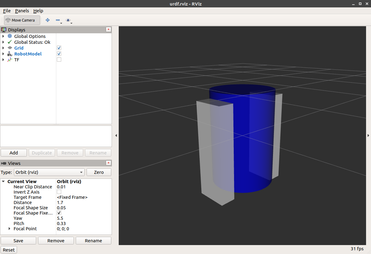
The body is now blue. We’ve defined a new material called “blue”, with the red, green, blue and alpha channels defined as 0,0,0.8 and 1 respectively. All of the values can be in the range [0,1]. This material is then referenced by the base_link’s visual element. The white material is defined similarly.
-
You could also define the material tag from within the visual element, and even reference it in other links. No one will even complain if you redefine it though.
-
You can also use a texture to specify an image file to be used for coloring the object
ros2 launch urdf_tutorial display.launch.py model:=urdf/04-materials.urdf

Finishing the Model?
Now we finish the model off with a few more shapes: feet, wheels, and head. Most notably, we add a sphere and a some meshes. We’ll also add few other pieces that we’ll use later.?[Source: 05-visual.urdf]
<?xml version="1.0"?>
<robot name="visual">

  <material name="blue">
    <color rgba="0 0 0.8 1"/>
  </material>
  <material name="black">
    <color rgba="0 0 0 1"/>
  </material>
  <material name="white">
    <color rgba="1 1 1 1"/>
  </material>

  <link name="base_link">
    <visual>
      <geometry>
        <cylinder length="0.6" radius="0.2"/>
      </geometry>
      <material name="blue"/>
    </visual>
  </link>

  <link name="right_leg">
    <visual>
      <geometry>
        <box size="0.6 0.1 0.2"/>
      </geometry>
      <origin rpy="0 1.57075 0" xyz="0 0 -0.3"/>
      <material name="white"/>
    </visual>
  </link>

  <joint name="base_to_right_leg" type="fixed">
    <parent link="base_link"/>
    <child link="right_leg"/>
    <origin xyz="0 -0.22 0.25"/>
  </joint>

  <link name="right_base">
    <visual>
      <geometry>
        <box size="0.4 0.1 0.1"/>
      </geometry>
      <material name="white"/>
    </visual>
  </link>

  <joint name="right_base_joint" type="fixed">
    <parent link="right_leg"/>
    <child link="right_base"/>
    <origin xyz="0 0 -0.6"/>
  </joint>

  <link name="right_front_wheel">
    <visual>
      <origin rpy="1.57075 0 0" xyz="0 0 0"/>
      <geometry>
        <cylinder length="0.1" radius="0.035"/>
      </geometry>
      <material name="black"/>
    </visual>
  </link>
  <joint name="right_front_wheel_joint" type="fixed">
    <parent link="right_base"/>
    <child link="right_front_wheel"/>
    <origin rpy="0 0 0" xyz="0.133333333333 0 -0.085"/>
  </joint>

  <link name="right_back_wheel">
    <visual>
      <origin rpy="1.57075 0 0" xyz="0 0 0"/>
      <geometry>
        <cylinder length="0.1" radius="0.035"/>
      </geometry>
      <material name="black"/>
    </visual>
  </link>
  <joint name="right_back_wheel_joint" type="fixed">
    <parent link="right_base"/>
    <child link="right_back_wheel"/>
    <origin rpy="0 0 0" xyz="-0.133333333333 0 -0.085"/>
  </joint>

  <link name="left_leg">
    <visual>
      <geometry>
        <box size="0.6 0.1 0.2"/>
      </geometry>
      <origin rpy="0 1.57075 0" xyz="0 0 -0.3"/>
      <material name="white"/>
    </visual>
  </link>

  <joint name="base_to_left_leg" type="fixed">
    <parent link="base_link"/>
    <child link="left_leg"/>
    <origin xyz="0 0.22 0.25"/>
  </joint>

  <link name="left_base">
    <visual>
      <geometry>
        <box size="0.4 0.1 0.1"/>
      </geometry>
      <material name="white"/>
    </visual>
  </link>

  <joint name="left_base_joint" type="fixed">
    <parent link="left_leg"/>
    <child link="left_base"/>
    <origin xyz="0 0 -0.6"/>
  </joint>

  <link name="left_front_wheel">
    <visual>
      <origin rpy="1.57075 0 0" xyz="0 0 0"/>
      <geometry>
        <cylinder length="0.1" radius="0.035"/>
      </geometry>
      <material name="black"/>
    </visual>
  </link>
  <joint name="left_front_wheel_joint" type="fixed">
    <parent link="left_base"/>
    <child link="left_front_wheel"/>
    <origin rpy="0 0 0" xyz="0.133333333333 0 -0.085"/>
  </joint>

  <link name="left_back_wheel">
    <visual>
      <origin rpy="1.57075 0 0" xyz="0 0 0"/>
      <geometry>
        <cylinder length="0.1" radius="0.035"/>
      </geometry>
      <material name="black"/>
    </visual>
  </link>
  <joint name="left_back_wheel_joint" type="fixed">
    <parent link="left_base"/>
    <child link="left_back_wheel"/>
    <origin rpy="0 0 0" xyz="-0.133333333333 0 -0.085"/>
  </joint>

  <joint name="gripper_extension" type="fixed">
    <parent link="base_link"/>
    <child link="gripper_pole"/>
    <origin rpy="0 0 0" xyz="0.19 0 0.2"/>
  </joint>

  <link name="gripper_pole">
    <visual>
      <geometry>
        <cylinder length="0.2" radius="0.01"/>
      </geometry>
      <origin rpy="0 1.57075 0 " xyz="0.1 0 0"/>
    </visual>
  </link>

  <joint name="left_gripper_joint" type="fixed">
    <origin rpy="0 0 0" xyz="0.2 0.01 0"/>
    <parent link="gripper_pole"/>
    <child link="left_gripper"/>
  </joint>

  <link name="left_gripper">
    <visual>
      <origin rpy="0.0 0 0" xyz="0 0 0"/>
      <geometry>
        <mesh filename="package://urdf_tutorial/meshes/l_finger.dae"/>
      </geometry>
    </visual>
  </link>

  <joint name="left_tip_joint" type="fixed">
    <parent link="left_gripper"/>
    <child link="left_tip"/>
  </joint>

  <link name="left_tip">
    <visual>
      <origin rpy="0.0 0 0" xyz="0.09137 0.00495 0"/>
      <geometry>
        <mesh filename="package://urdf_tutorial/meshes/l_finger_tip.dae"/>
      </geometry>
    </visual>
  </link>
  <joint name="right_gripper_joint" type="fixed">
    <origin rpy="0 0 0" xyz="0.2 -0.01 0"/>
    <parent link="gripper_pole"/>
    <child link="right_gripper"/>
  </joint>

  <link name="right_gripper">
    <visual>
      <origin rpy="-3.1415 0 0" xyz="0 0 0"/>
      <geometry>
        <mesh filename="package://urdf_tutorial/meshes/l_finger.dae"/>
      </geometry>
    </visual>
  </link>

  <joint name="right_tip_joint" type="fixed">
    <parent link="right_gripper"/>
    <child link="right_tip"/>
  </joint>

  <link name="right_tip">
    <visual>
      <origin rpy="-3.1415 0 0" xyz="0.09137 0.00495 0"/>
      <geometry>
        <mesh filename="package://urdf_tutorial/meshes/l_finger_tip.dae"/>
      </geometry>
    </visual>
  </link>

  <link name="head">
    <visual>
      <geometry>
        <sphere radius="0.2"/>
      </geometry>
      <material name="white"/>
    </visual>
  </link>
  <joint name="head_swivel" type="fixed">
    <parent link="base_link"/>
    <child link="head"/>
    <origin xyz="0 0 0.3"/>
  </joint>

  <link name="box">
    <visual>
      <geometry>
        <box size="0.08 0.08 0.08"/>
      </geometry>
      <material name="blue"/>
    </visual>
  </link>

  <joint name="tobox" type="fixed">
    <parent link="head"/>
    <child link="box"/>
    <origin xyz="0.1814 0 0.1414"/>
  </joint>
</robot>

ros2 launch urdf_tutorial display.launch.py model:=urdf/05-visual.urdf

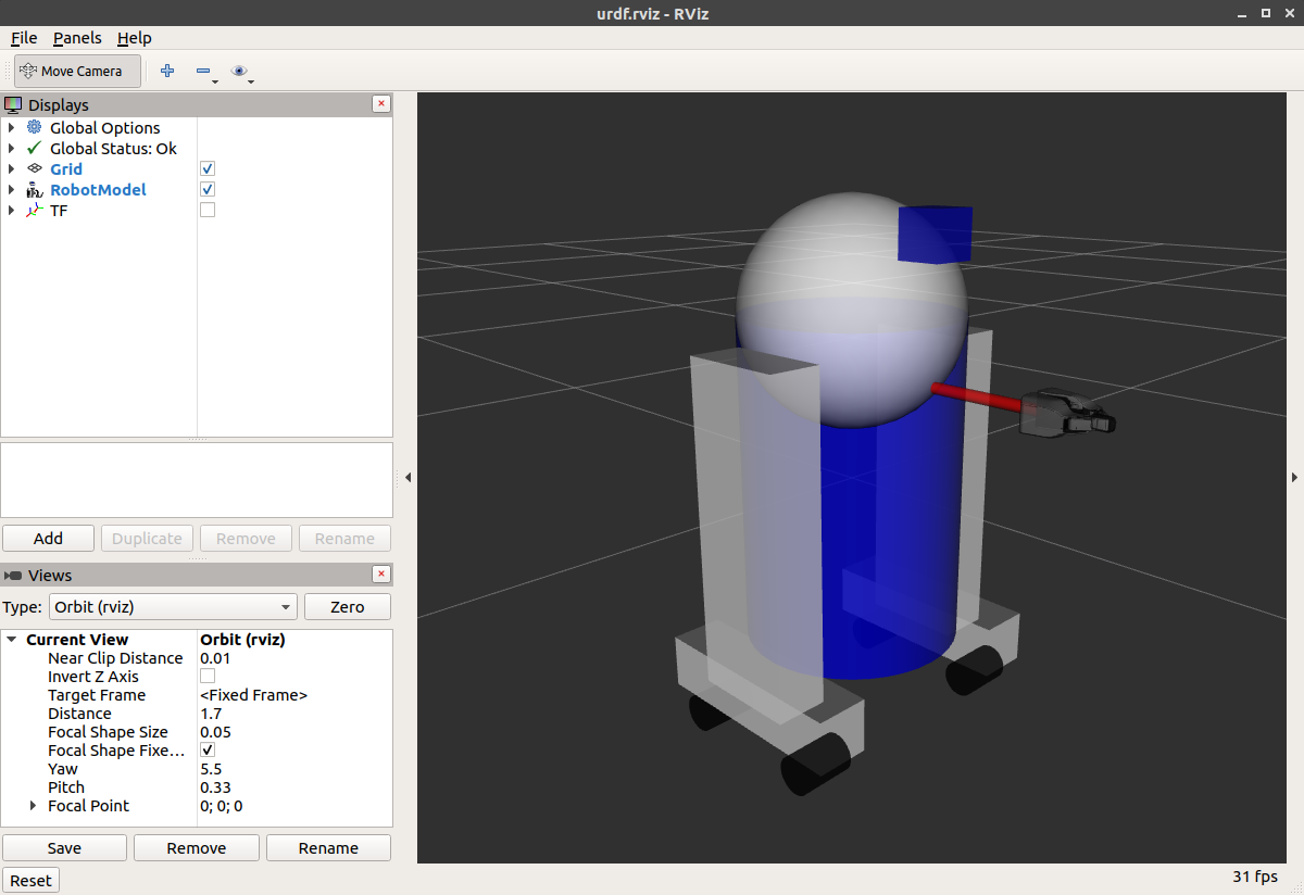
How to add the sphere should be fairly self explanatory:
<link name="head">
  <visual>
    <geometry>
      <sphere radius="0.2"/>
    </geometry>
    <material name="white"/>
  </visual>
</link>

The meshes here were borrowed from the PR2. They are separate files which you have to specify the path for. You should use the?package://NAME_OF_PACKAGE/path?notation. The meshes for this tutorial are located within the?urdf_tutorial?package, in a folder called meshes.
<link name="left_gripper">
  <visual>
    <origin rpy="0.0 0 0" xyz="0 0 0"/>
    <geometry>
      <mesh filename="package://urdf_tutorial/meshes/l_finger.dae"/>
    </geometry>
  </visual>
</link>

-
The meshes can be imported in a number of different formats. STL is fairly common, but the engine also supports DAE, which can have its own color data, meaning you don’t have to specify the color/material. Often these are in separate files. These meshes reference the?
.tif?files also in the meshes folder. -
Meshes can also be sized using relative scaling parameters or a bounding box size.
-
We could have also referred to meshes in a completely different package.
There you have it. A R2D2-like URDF model. Now you can continue on to the next step,?making it move.
本文来自互联网用户投稿,该文观点仅代表作者本人,不代表本站立场。本站仅提供信息存储空间服务,不拥有所有权,不承担相关法律责任。 如若内容造成侵权/违法违规/事实不符,请联系我的编程经验分享网邮箱:veading@qq.com进行投诉反馈,一经查实,立即删除!