脉冲压缩及MATLAB仿真
文章目录
前言
本文对脉冲压缩的内容以思维导图的形式呈现,有关仿真部分进行了讲解实现。
一、脉冲压缩
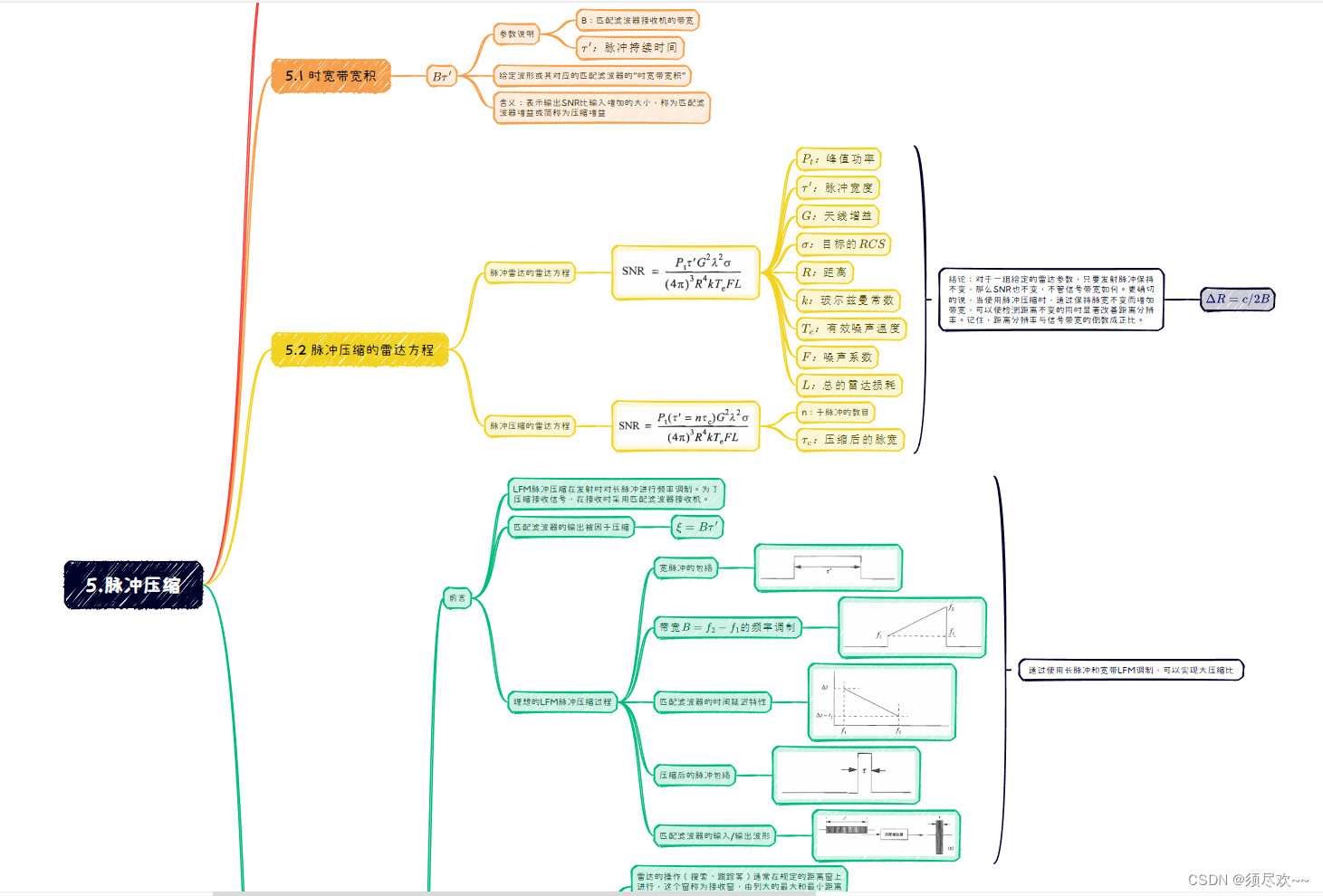
脉冲压缩思维导图如下图所示,如有需求请到文章末尾端自取。
二、MATLAB 仿真
1、LFM 脉冲压缩+匹配滤波实现测距
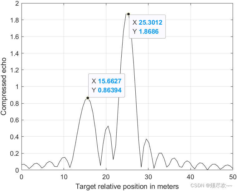
本例子中检测两个 RCS 分别是 σ 1 \sigma_1 σ1?= 1 m 2 1m^2 1m2 和 σ 2 \sigma_2 σ2?= 2 m 2 2m^2 2m2 的目标,且在接收窗的相对距离为15m 和 25m,这两个目标在时间上的间隔不足以被用来分辨。
LFM 归一化的复数发射信号形式:

上式参数含义如下:
- τ ′ :脉宽 \tau':脉宽 τ′:脉宽;
- μ = B / τ \mu=B/\tau μ=B/τ;
- B :带宽 B:带宽 B:带宽;
雷达从目标接收的回波信号表达式:

上式参数含义如下:
- a 1 :正比于目标的 R C S 、天线增益及距离衰减 a_1:正比于目标的RCS、天线增益及距离衰减 a1?:正比于目标的RCS、天线增益及距离衰减;
- τ 1 :时间延迟 \tau_1:时间延迟 τ1?:时间延迟;
- τ 1 = 2 R 1 / c \tau_1=2R_1/c τ1?=2R1?/c;
- R 1 :目标距离 R_1:目标距离 R1?:目标距离
所要求的最小样本数:
N
≥
2
B
τ
′
N\geq2B\tau'
N≥2Bτ′
因此总共
2
B
τ
′
2B\tau'
2Bτ′ 个实样本或
B
τ
′
B\tau'
Bτ′ 个复样本,足以完全描述时宽为
τ
′
\tau'
τ′ 带宽为
B
B
B 的 LFM 波形。例如一个时宽
τ
′
=
20
μ
s
\tau'=20\mu s
τ′=20μs,带宽
B
=
5
M
H
z
B=5MHz
B=5MHz 的LFM 信号,要求 200 个实样本来确定输入信号(I 路 100 个样本,Q 路 100 个样本)
雷达距离分辨率公式: Δ R = c / 2 B \Delta R=c/2B ΔR=c/2B,目标之间的距离需要大于距离分辨率的距离,否则难以区分目标。
①、MATLAB 源码
matched_filter.m
function [y] = matched_filter(nscat,taup,b,rrec,scat_range,scat_rcs,winid)
eps = 1.0e-16;      % 定义了一个很小的常量,用于处理数值计算中的舍入误差,此变量未用到
% time bandwidth product
time_B_product = b * taup;      % 计算时间带宽乘积
if(time_B_product < 5 )
    fprintf('************ Time Bandwidth product is TOO SMALL ***************')
    fprintf('\n Change b and or taup')
  return
end
% speed of light
c = 3.e8;
% number of samples
% 在匹配滤波器的应用中,时间带宽积和采样点数之间存在一定的关系。通常情况下,为了准确地捕捉信号的特征并避免信息的丢失,采样点数应该足够多,以确保在时间域内有足够的采样点来表示信号的特征。一般而言,采样点数应该大于等于时间带宽积,以确保恢复出精确的信号特征。
n = fix(5 * taup * b);  % 乘以5的目的是为了提供一定的冗余,以防止信号特征在时间域上的模糊化。
% initialize input, output and replica vectors
x(nscat,1:n) = 0.;
y(1:n) = 0.;
replica(1:n) = 0.;
% determine proper window
if( winid == 0.)
   win(1:n) = 1.;
end
if(winid == 1.);
    win = hamming(n)';
end
if( winid == 2.)
    win = kaiser(n,pi)';
end
if(winid == 3.)
    win = chebwin(n,60)';
end
% check to ensure that scatterers are within recieve window
index = find(scat_range > rrec);
if (index ~= 0)
    'Error. Receive window is too large; or scatterers fall outside window'
  return
end
% calculate sampling interval
t = linspace(-taup/2,taup/2,n);
replica = exp(i * pi * (b/taup) .* t.^2);
figure(1)
subplot(2,1,1)
plot(t,real(replica))
ylabel('Real (part) of replica')
xlabel('time in seconds')
grid
subplot(2,1,2)
sampling_interval = taup / n;       % 采样间隔
freqlimit = 0.5/ sampling_interval; % 通过将0.5除以采样间隔,可以计算出信号的最高频率,在这个频率以下的信号可以被准确地表示和恢复。
freq = linspace(-freqlimit,freqlimit,n);
plot(freq,fftshift(abs(fft(replica))));
ylabel('Spectrum of replica')
xlabel('Frequency in Hz')
grid
% 对于每个散射体,计算其距离range对应的散射信号,并将其与输出向量y相加。
 for j = 1:1:nscat
    range = scat_range(j) ;
    x(j,:) = scat_rcs(j) .* exp(i * pi * (b/taup) .* (t +(2*range/c)).^2) ; % 回波信号
    y = x(j,:)  + y;    % 回波信号相加
end
figure(2)
y = y .* win;
plot(t,real(y),'k')
xlabel ('Relative delay - seconds')
ylabel ('Uncompressed echo')
grid
out =xcorr(replica, y);     % 计算发射信号和回波信号的相关性
out = out ./ n;             % 归一化
s = taup * c /2;            % 计算脉冲宽度taup对应的距离步长s
Npoints = ceil(rrec * n /s);	% LFM 的距离步长为 s 对应 n 个点,则 rrec 对应的点数
dist =linspace(0, rrec, Npoints);   % 基于接收窗口的范围rrec计算距离向量dist
delr = c/2/b;
figure(3)
plot(dist,abs(out(n:n+Npoints-1)),'k')
xlabel ('Target relative position in meters')
ylabel ('Compressed echo')
grid
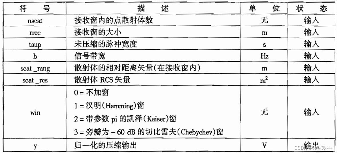
fig5_3.m
% use this program to reproduce Fig. 5.2 of text
clear all
close all
nscat = 2; %two point scatterers
taup = 10e-6; % 10 microsecond uncompressed pulse
b = 50.0e6; % 50 MHz bandwdith
rrec = 50 ; % 50 meter processing window
scat_range = [15 25] ; % scattterers are 15 and 25 meters into window
scat_rcs = [1 2]; % RCS 1 m^2 and 2m^2
winid = 0; %no window used
[y] = matched_filter(nscat,taup,b,rrec,scat_range,scat_rcs,winid);
②、仿真结果
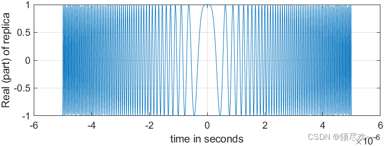
1) LFM 时域波形
程序中设置的时宽为 10us
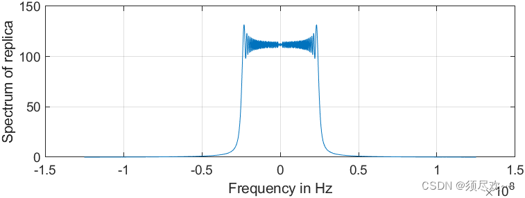
2) LFM 频域波形
信号的最高频率为 125MHz,带宽为 50MHz
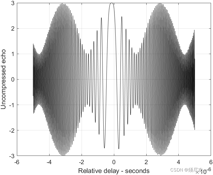
3) 两个未分辨目标的合成回波信号
4) 脉冲压缩检测距离
2、去协处理仿真
假设 I 个目标位于距离
R
1
、
R
2
R_1、R_2
R1?、R2? 等处(
R
1
<
R
2
<
R
I
R_1<R_2<R_I
R1?<R2?<RI?),根据叠加原理,总信号为:

其中 {
a
i
(
t
)
;
i
=
1
,
2
,
.
.
.
I
a_i(t);i=1,2,...I
ai?(t);i=1,2,...I} 与目标截面积、天线增益和距离衰减成正比。时间 {
τ
i
=
2
R
i
/
c
;
i
=
1
,
2
,
.
.
.
,
I
\tau_i=2R_i/c;i=1,2,...,I
τi?=2Ri?/c;i=1,2,...,I} 表示双程时间延迟,其中
τ
1
\tau_1
τ1? 对应接收窗起点。
则 LPF 输出端的总信号可以写为:

①、MATLAB 源码
stretch.m
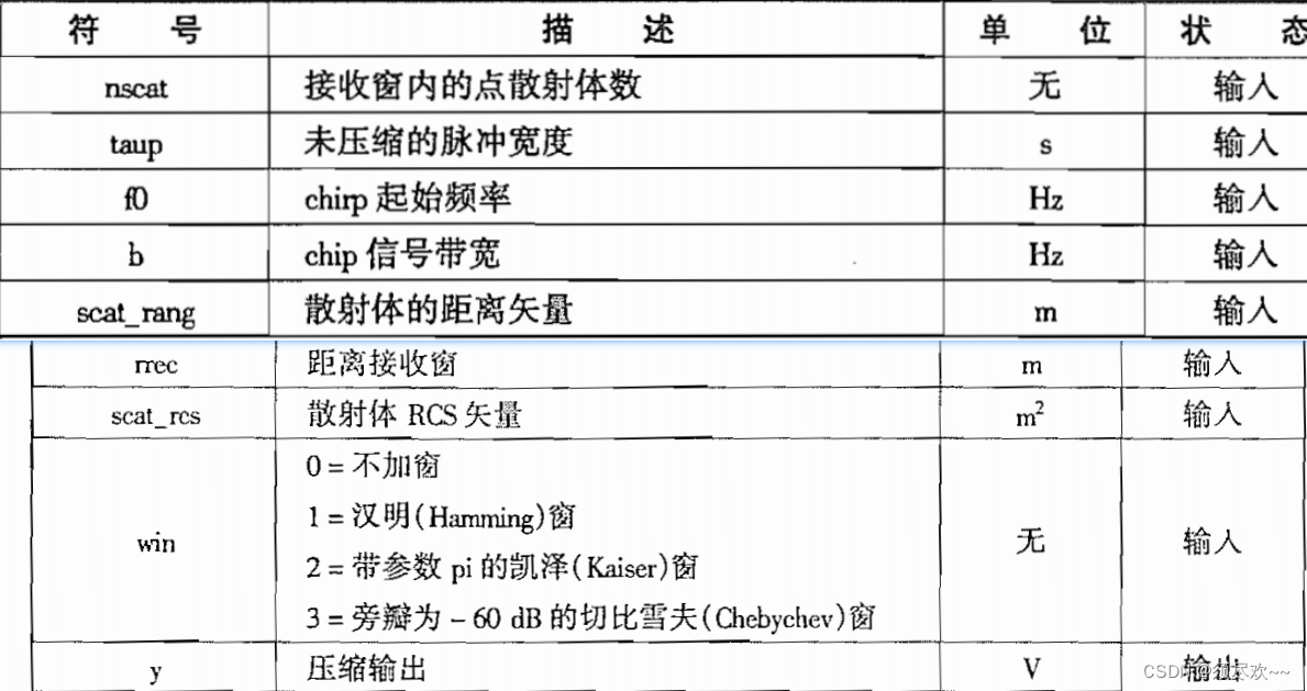
function [y] = stretch(nscat,taup,f0,b,rrec,scat_range,scat_rcs,winid)
eps = 1.0e-16;              % 未用到
htau = taup / 2.;           % 未用到
c = 3.e8;
trec = 2. * rrec / c;       % 接收窗时间大小
n = fix(2. * trec * b);     % 所要求的最小样本数,足以完全描述时宽为接收窗大小,带宽为 b 的 LFM 波形
m = power_integer_2(n);     % 计算一个大于等于 n 的最小的 2 的整数幂。
nfft = 2.^m;                % 接收窗 FFT 的长度
x(nscat,1:n) = 0.;
y(1:n) = 0.;
if( winid == 0.)
   win(1:n) = 1.;
   win =win';
else
   if(winid == 1.)
      win = hamming(n);
   else
      if( winid == 2.)
         win = kaiser(n,pi);
      else
         if(winid == 3.)
            win = chebwin(n,60);
         end
      end
   end
end
deltar = c / 2. / b;            % 每个带宽单位内的传播时间
max_rrec = deltar * nfft / 2.;  % 最大可接收的传播距离
maxr = max(scat_range);
if(rrec > max_rrec | maxr >= rrec ) % 判断接收窗口的大小是否合理
   'Error. Receive window is too large; or scatterers fall outside window'
   return
end
t = linspace(0,taup,n);
% 通过循环计算每个散射体对应的压缩回波信号。首先,根据散射体的距离 range 计算相位 psi1 和 psi2,然后使用指数函数计算每个散射体对应的回波信号,并将其累加到 y 中。
for j = 1:1:nscat
    range = scat_range(j);% + rmin;     % 目标距离
   psi1 = 4. * pi * range * f0 / c - ...
      4. * pi * b * range * range / c / c/ taup;
   psi2 = (2*4. * pi * b * range / c / taup) .* t;
   x(j,:) = scat_rcs(j) .* exp(i * psi1 + i .* psi2);
   y = y + x(j,:);
end
figure(1)
plot(t,real(y),'k')
xlabel ('Relative delay - seconds')
ylabel ('Uncompressed echo')
grid
ywin = y .* win';
yfft = fft(y,n) ./ n;
out= fftshift(abs(yfft));
figure(2)
delinc = rrec/ n;
%dist = linspace(-delinc-rrec/2,rrec/2,n);
dist = linspace((-rrec/2), rrec/2,n);
plot(dist,out,'k')
xlabel ('Relative range in meters')
ylabel ('Compressed echo')
axis auto
grid
test.m
clear all
close all
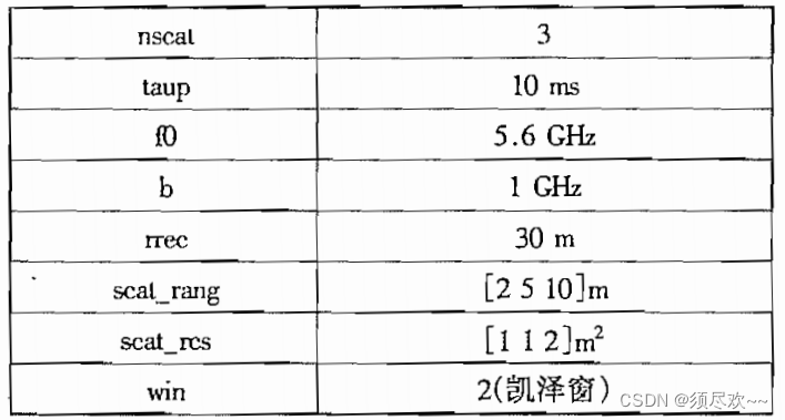
nscat = 3;      % three point scatterers
taup = 1e-2;    % 10 millisecond uncompressed pulse
f0 = 5.6e9;     % 5.6 GHz
b = 1e9;        % 1 GHz bandwdith
rrec = 30;      % 30 meter processing window
scat_range = [2 5 10] ; % scattterers are 2 and 5 and 10 meters into window
scat_rcs = [1 1 2]; % RCS 1 m^2 and 1m^2 and 2m^2
winid = 2; % kaiser window
[y] = stretch(nscat,taup,f0,b,rrec,scat_range,scat_rcs,winid);
②、仿真结果
1) 未压缩回波信号,3个目标不能分辨
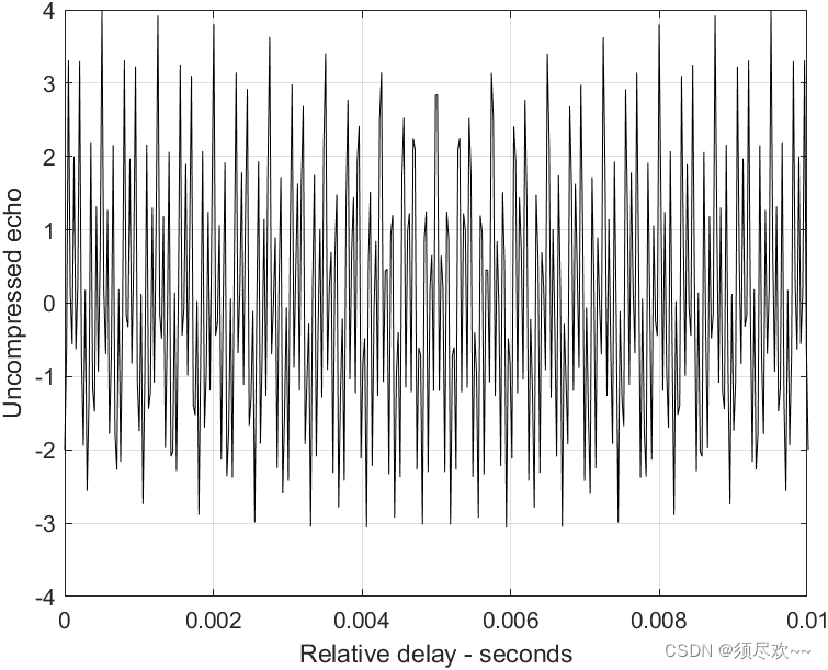
2) 压缩回波信号,3个日标可以分辨

3、目标速度引起的失真
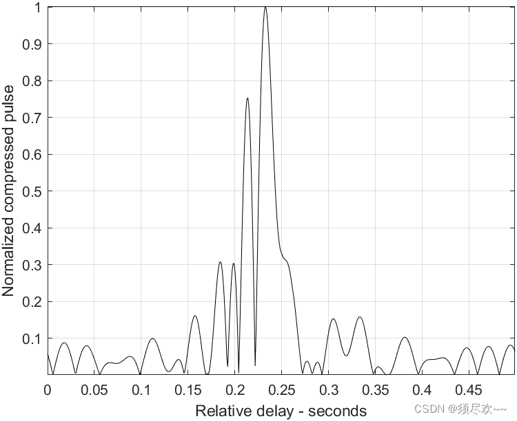
当目标径向速度非零时,接受脉冲宽度会被时间膨胀因子扩展(或压缩)。另外,接收脉冲的中心频率会以多普勒频率的大小偏移。
由目标径向速度引起的失真校正可以使用下面方法实现:在几个脉冲的时间内,雷达处理器估计跟踪目标的径向速度,然后改变下一个发射脉冲的chirp斜率和脉冲宽度,以补偿估计出的多普勒频率和时间膨胀。
目标速度引起的失真仿真如下:
①、MATLAB 源码
% use this program to reproduce Fig. 5.14 of text
clear all
eps = 1.5e-5;
t = 0:0.001:.5;
y = chirp(t,0,.25,20);
figure(1)
plot(t,y);
yfft = fft(y,512) ;
ycomp = fftshift(abs(ifft(yfft .* conj(yfft))));
maxval = max (ycomp);
ycomp = eps + ycomp ./ maxval;
figure(1)
del = .5 /512.;
tt = 0:del:.5-eps;
plot (tt,ycomp,'k')
axis tight
xlabel ('Relative delay - seconds');
ylabel('Normalized compressed pulse')
grid
%change center frequency
y1 = chirp (t,0,.25,21);
y1fft = fft(y1,512);
y1comp = fftshift(abs(ifft(y1fft .* conj(yfft))));
maxval = max (y1comp);
y1comp = eps + y1comp ./ maxval;
figure(2)
plot (tt,y1comp,'k')
axis tight
xlabel ('Relative delay - seconds');
ylabel('Normalized compressed pulse')
grid
%change pulse width
t = 0:0.001:.45;
y2 = chirp (t,0,.225,20);
y2fft = fft(y2,512);
y2comp = fftshift(abs(ifft(y2fft .* conj(yfft))));
maxval = max (y2comp);
y2comp = eps + y2comp ./ maxval;
figure(3)
plot (tt,y2comp,'k')
axis tight
xlabel ('Relative delay - seconds');
ylabel('Normalized compressed pulse')
grid
②、仿真结果
1) LFM 信号
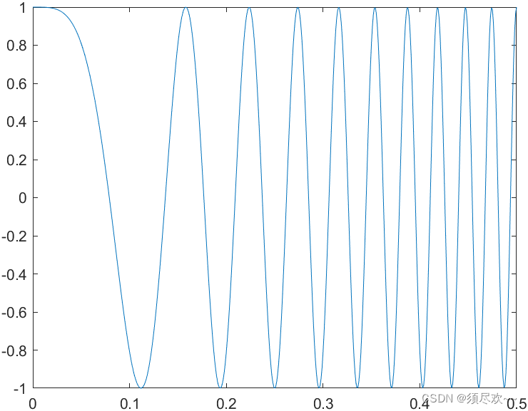
2) 脉冲压缩处理器的压缩脉冲输出
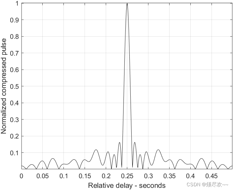
3) 失配的压缩脉冲,5%多普勒频移
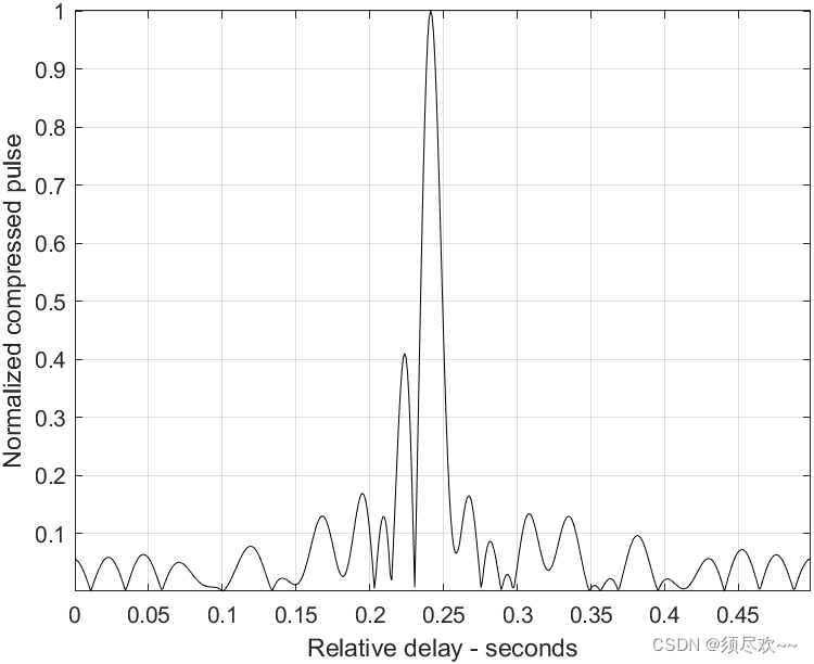
4) 失配的压缩脉冲,10%时间膨胀
三、资源自取
我的qq:2442391036,欢迎交流!
本文来自互联网用户投稿,该文观点仅代表作者本人,不代表本站立场。本站仅提供信息存储空间服务,不拥有所有权,不承担相关法律责任。 如若内容造成侵权/违法违规/事实不符,请联系我的编程经验分享网邮箱:veading@qq.com进行投诉反馈,一经查实,立即删除!
