计算机网络课程设计-企业网三层架构
(单人版)
摘 要
本篇报告主要解决了为一家名为西宫的公司网络搭建问题,该网络采用企业网三层架构对完了过进行设计。首先使用以太网中继,主要使用VLAN划分的技术来划定不同部门。使用MSTP对每个组配置生成树,防止交换机的冗余链路产生环路。采用VRRP技术,为不同的VLAN配置虚拟网关,并且配置网关冗余,提高网络稳定性。并且在汇聚层做配置,达到汇聚层、根网桥和主网关三合一的效果,提高转发效率。使用DHCP技术为接入层设备配置IP地址,解决员工上网需求。使用OSPF配置路由,使网络内网联通。配置NAT,使网络可以联通外网,全网可达。同时良好的IP规划,对汇聚层的路由进行汇总提高转发效率。配置http服务器和dns服务器,实现可以用域名对公司内部资源的访问,上传与下载公司有关的各类信息。
目 录
一、设计任务概述
1.1 设计目的
设计一个稳定的网络结构,旨为公司提供良好的网络服务,主公司分公司之间可以互通。要求:IP地址规划,可以方便汇总,提高转发效率。对设备做冗余,提高网络的稳定性以及容错能力。策略优化,一些细小的优化,帮助网络更流畅。
1.2 项目任务和要求
对公司网络需求进行分析,确定网络应该如何搭建。网络拓扑设计,良好的网络拓扑设计可以提高网络的转发速率以及网络可以提高网络的稳定性。实现良好的IP地址的规划,路由汇总方便,提高转发效率。网络全网可达可以ping通外网,获取网络上的资源。网络稳定性好,有一定的设备冗余、线路冗余,当网络中设备出现问题时对网络的容错性可以提高。
1.3 参考资料
[1]Jeff Doyle,Jennifer Carroll.TCP/IP路由技术(第一卷)[M].葛建立,吴剑章,译.人民邮电出版社,2007.
[2]谢希仁,计算机网络(第8版)[M].电子工业出版社,2021.
二、项目开发环境
软件环境:Windows 10
硬件要求:500G硬盘+16GB+AMD Ryzen 9 5900HX with Radeon Graphics
开发工具:eNSP
机器IP地址: 192.168.199.216
机器MAC地址:A4-B1-C1-D8-A6-44
三、项目需求分析
一家名为西宫的公司,公司分为主公司和分公司。主公司和分公司都是下设三个部门:销售部、财务部、研发部,针对三个部门做出相应的网络部署。要求全网可达,网络稳定性好。同时,要解决对于西宫公司三个部门之间网络的如何联通,以及相互之间的访问情况。还需搭建相应的HTTP服务器和DNS服务器实现公司内部资源的访问,上传与下载公司有关的各类信息。对于这些问题我们打算网络采用企业网三层架构部署网络。主公司用一台路由器当作核心层,负责对来自汇聚层的数据进行尽可能快速的转发。两台三层交换机当做汇聚层,并且用STP和VRRP技术对设备做一个网关冗余和根网桥冗余,并且调整网关和根网桥的位置,让其处在汇聚层,达产汇聚层根网桥,网关三合一的效果,提高转发效率。汇聚层可以做出策略用以将接入层的数据汇集起来,然后可以依据一些策略对数据、信息等实施控制。比如说,可以在接入层接口上做边缘接口,让接入层接口不发BDU取打扰其他设备。降低网络资源占用两,提高网络收敛转发速率。在接入层可以连接多台交换机提供丰富的接口,负责接入不同部门的员工,并且接口可以连接WiFi,使其获得网络服务。配置http服务器,实现公司内部资源的访问,上传与下载公司有关的各类信息。分公司同样使用一台路由器当作核心层负责对来自汇聚层的数据进行快速转发,汇聚层采用一台三层交换机,帮助接入层进行数据转发,并且采用SVI和VRRP技术当作各个部门的网关。接入层采用二层交换机提供大量接口,负责接入不同的员工,使其可以正常上网,并且可以连接WIFI,使其获得网络服务。分公司和主公司之间可以相互通信,并且分公司可以登陆位于主公公司HTTP服务器,实现公司内部资源的访问,上传与下载公司有关的各类信息。
四、项目设计和实现
4.1 总体设计
网络采用企业网三层架构部署网络。主公司用一台路由器当作核心层,负责对来自汇聚层的数据进行尽可能快速的转发。两台三层交换机当做汇聚层,并且用STP和VRRP技术对设备做一个网关冗余和根网桥冗余,并且调整网关和根网桥的位置,让其处在汇聚层,达产汇聚层根网桥,网关三合一的效果,提高转发效率。汇聚层可以做出策略用以将接入层的数据汇集起来,然后可以依据一些策略对数据、信息等实施控制。比如说,可以在接入层接口上做边缘接口,让接入层接口不发BDU取打扰其他设备。降低网络资源占用两,提高网络收敛转发速率。在接入层可以连接多台交换机提供丰富的接口,负责接入不同部门的员工,并且接口可以连接WiFi,使其获得网络服务。配置http服务器,实现公司内部资源的访问,上传与下载公司有关的各类信息。分公司同样使用一台路由器当作核心层负责对来自汇聚层的数据进行快速转发,汇聚层采用一台三层交换机,帮助接入层进行数据转发,并且采用SVI和VRRP技术当作各个部门的网关。接入层采用二层交换机提供大量接口,负责接入不同的员工,使其可以正常上网,并且可以连接WIFI,使其获得网络服务。分公司和主公司之间可以相互通信,并且分公司可以登陆位于主公公司HTTP服务器,实现公司内部资源的访问,上传与下载公司有关的各类信息。
网络拓扑:

具体IP分配:
| 设备 | 网段 | 网关 | 备注 |
| PC1 | 172.16.1.0/24 | 172.16.1.254 | IP:172.16.1.253 |
| PC5 | 172.16.2.0/24 | 172.16.2.254 | IP:172.16.2.253 |
| PC6 | 172.16.3.0/24 | 172.16.3.254 | IP:172.16.3.253 |
| PC7 | 192.168.3.0/24 | 192.168.3.254 | IP:192.168.3.253 |
| PC8 | 192.168.2.0/24 | 192.168.2.254 | IP:192.168.2.253 |
| PC9 | 192.168.0.0/24 | 192.168.0.254 | IP:192.168.0.253 |
| Client1 | 172.16.1.0/24 | 172.16.1.254 | IP:172.16.1.101 |
| Client2 | 192.168.0.0/24 | 192.168.0.254 | 192.168.0.101 |
| http | 172.16.0.0/24 | 172.16.0.101 | IP:172.16.0.100 |
| dns | 172.16.0.0/24 | 172.16.0.101 | IP:172.16.0.200 |
| R1-ISO | 12.1.1.0/24 | R1:12.1.1.1 ISO:12.1.1.2 | |
| R1-LSW1 | 172.16.0.0/30 | R1:172.16.0.1 LSW1:172.16.0.2 | |
| R1-LSW2 | 172.16.0.4/30 | R1:172.16.0.5 LSW2:172.16.0.6 | |
| R1-R3 | 192.168.1.0/30 | R1:192.168.1.1 R3:192.168.1.2 | |
| R1 | G4/0/0:172.16.0.101 | ||
| LSW1 | vlanif1:172.16.1.0/24 vlanif2:172.16.2.0/24 vlanif3:172.16.3.0/24 | vlanif1:172.16.1.1 vlanif2:172.16.2.1 vlanif3:172.16.3.1 vlan1虚拟网关:172.16.1.254 vlan2虚拟网关:172.16.2.254 vlan3虚拟网关:172.16.3.254 | |
| LSW2 | vlanif1:172.16.1.0/24 vlanif2:172.16.2.0/24 vlanif3:172.16.3.0/24 | vlanif1:172.16.1.2 vlanif2:172.16.2.2 vlanif3:172.16.3.2 vlan1虚拟网关:172.16.1.254 vlan2虚拟网关:172.16.2.254 vlan3虚拟网关:172.16.3.254 | |
| A-SW4 | vlanif1:192.168.0.0/24 vlanif2:192.168.2.0/24 vlanif3:192.168.3.0/24 | vlanif1:192.168.0.1 vlanif2:192.168.2.1 vlanif3:192.168.3.1 vlan1虚拟网关:192.168.0.254 vlan2虚拟网关:192.168.2.254 vlan3虚拟网关:192.168.3.254 | |
| ISO | 6.6.6.0/24 | 环回模拟外网:6.6.6.6 | |
| R3-A-SW4 | 192.168.1.4/30 | R3:192.168.1.5 A-SW4:192.168.1.6 |
4.2?功能设计
由于本网络MSTP采用的是基于组的生成树,对汇聚层链路要求较高所以将SW1 G0/0/22和G0/0/23口使用以太网中继技术绑定在一起,提高了两个链路之间的带宽,提高了两个设备之间链路的可靠性。当其中一个链路出现问题时,另一个链路可以正常使用,确保了网络稳定性。同时这个结构只作用在相邻的两个设备之间,应用起来也比较简单。然后创建VLAN,划分TRUNK干道,不同VLAN代表不同部门,不同VLAN之间不可以广播通信,提高了网络的安全性,同时基于VLAN可以更好的进行一些配置,按照不同部门的性质可以做一些策略。再之后配置MSTP,确保交换机之间的通畅,不会产生交换风暴。同时配置的是基于组的生成树,VLAN1是一个生成树,VLAN2和VLAN3是一个生成树,这样不同的组配置的生成树,实现了网络的冗余,其中一个生成树发生故障,其他生成树依然可以保证网络的正常运行。由于MSTP支持多个生成树,可以一定程度上缩短网络收敛时间,同时由于时多个生成树共享同一端口,网络还实现了流量的负载均衡和优化,这样网络的带宽得以提高。同时在二层交换机上还配置了端口映射这个样子这些端口就不会频繁的接收BPDU这样网络速率就会提高了。配置SVI帮助管理VLAN。然后我配置了VRRP,配置了网关冗余,保证了网络的持续可用性,同时MSTP和VRRP一起使用有多个逻辑拓扑,提高了网络的性能和可用性。然后配置DHCP自动获取IP,同时配置主公司OSPF。
4.3?系统实现
1、以太网中继:
SW1:
[sw1]interface Eth-Trunk 0
[sw1]interface GigabitEthernet 0/0/22
[sw1-GigabitEthernet0/0/22]eth-trunk 0
[sw1]interface GigabitEthernet 0/0/23
[sw1-GigabitEthernet0/0/23]eth-trunk 0
SW2配置域SW1相同
2、创建VLAN,接口划入VLAN:
SW1:
配置首先创建一个临时群组
[sw1]port-group group-member g0/0/1?to g0/0/2?Eth-Trunk 0
[sw1-port-group]port link-type trunk
[sw1-port-group]port trunk allow-pass vlan 2 3
SW2与SW1配置同理
SW3:
[sw3-Ethernet0/0/2]port default vlan 2
[sw3-Ethernet0/0/3]port default vlan 3
[sw3]port-group group-member g0/0/1 to g0/0/2
[sw3-port-group]port link-type trunk
[sw3-port-group]port trunk allow-pass vlan 2 3
SW4配置与SW3配置同理
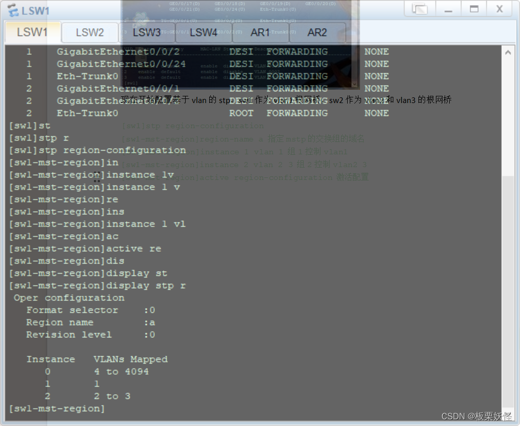
3、现在开始配置基于VLAN的STP,SW1作为VLAN1根网桥,SW2作为VLAN2和VLAN3的根网桥,同时两个交换机互为VLAN的备份:
[sw1]stp region-configuration
[sw1-mst-region]region-name a?
[sw1-mst-region]instance 1 vlan 1?
[sw1-mst-region]instance 2 vlan 2 3?
[sw1-mst-region]active region-configuration
现在组1放置vlan1组2放置vlan2 和vlan3 组0放置其他vlan,然后在其他三台台交换机上配置,配置与与在SW1上配置相同
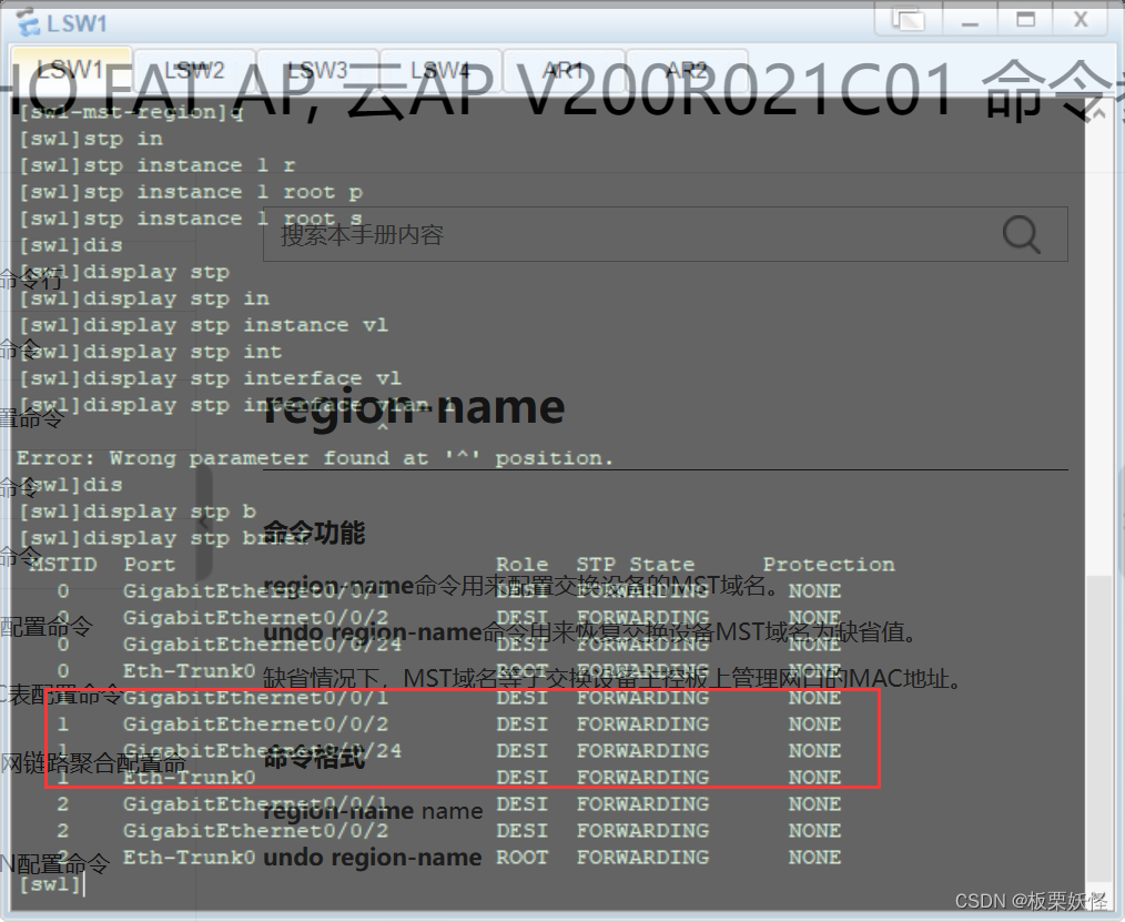
4、调整生成树现在配置让sw1当组1的主根,sw2当组2的备用根
[sw1]stp instance 1 root primary
[sw2]stp instance 1?root secondary
[sw1]stp instance 2?root secondary?
[sw2]stp instance 2?root primary
然后为了将来考虑,我们现在调整一下组0的根网桥将组0的根网桥放在sw1,备用放在sw2
[sw1]stp instance 0?root primary
[sw2]stp instance 0?root secondary
5、配置边缘接口
[sw3]port-group group-member e0/0/1 to e0/0/22
[sw3-port-group]stp edged-port enable
6、配置WIFI接口
[sw3-Ethernet0/0/3]stp instance 0 port priority 16
7、配置SVI
[sw1]interface vlan 1
[sw1-Vlanif1]ip address 172.16.1.1 24
[sw1]interface vlan 2
[sw1-Vlanif2]ip address 172.16.2.1 24
[sw1]interface vlan 3
[sw1-Vlanif3]ip address 172.16.3.1 24
[sw2]interface vlan 1
[sw2-Vlanif1]ip address 172.16.1.2?24
[sw2]interface vlan 2
[sw2-Vlanif2]ip address 172.16.2.2?24
[sw2]interface vlan 3
[sw2-Vlanif3]ip address 172.16.3.2?24
8、配置网关冗余和上行链路追踪
让vlan1的主网关是sw1备用网关是sw2
[sw1-Vlanif1]vrrp vrid 1 virtual-ip 172.168.1.254
[sw1-Vlanif1]vrrp vrid ?1 priority 101
[sw1-Vlanif1]vrrp vrid ?1 track interface g0/0/24 reduced 20?
[sw2-Vlanif1]vrrp vrid 1 virtual-ip 172.168.1.254
让sw2当vlan2和vlan3的主网关,sw1当vlan2和vlan3的备用网关,配置与vlan1的配置相同
9、配置DHCP
[sw2-ip-pool-vlan1] gateway-list 172.16.1.254
[sw2-ip-pool-vlan1] network 172.16.1.0 mask 255.255.255.0
[sw2-ip-pool-vlan1] dns-list 8.8.8.8 114.114.114.114
[sw2-ip-pool-vlan1]ip pool vlan2
Info:It's successful to create an IP address pool.
[sw2-ip-pool-vlan2] gateway-list 172.16.2.254
[sw2-ip-pool-vlan2] network 172.16.2.0 mask 255.255.255.0
[sw2-ip-pool-vlan2] dns-list 8.8.8.8 114.114.114.114
[sw2-ip-pool-vlan2]ip pool vlan3
Info:It's successful to create an IP address pool.
[sw2-ip-pool-vlan3] gateway-list 172.16.3.254
[sw2-ip-pool-vlan3] network 172.16.3.0 mask 255.255.255.0
[sw2-ip-pool-vlan3] dns-list 8.8.8.8 114.114.114.114
[sw1-Vlanif1]dhcp select global
[sw1-Vlanif2]dhcp select global
[sw1-Vlanif3]dhcp select global
五、系统运行和测试
1、以太网中继
查看接口配置后查看看发现两个口都在eth-trunk0口中,配置成功

查看vlan g0/0/22和g0/0/23不见了取而代之的是eth-trunk 0接口

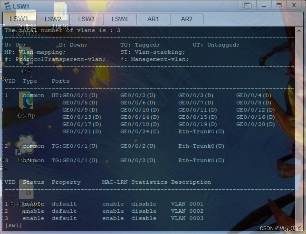
2、查看VLAN

3、查看STP树的分组

4、查看根网桥
5、查看VRRP配置

6、DHCP应用成功

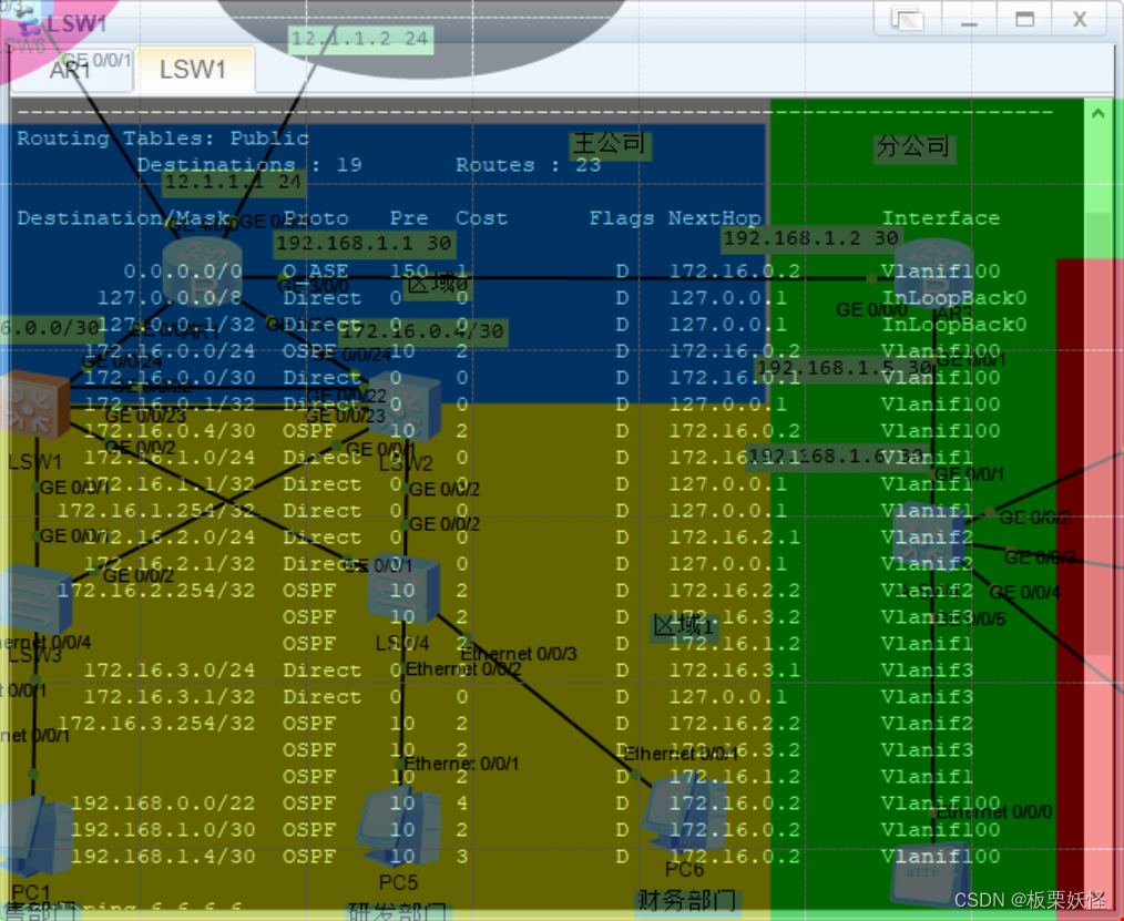
7、查看ospf配置


8、测试ping通外网

9、测试客户端登陆服务器

10、分公司ping通主公司

11、分公司客户端是否可以访服务器

12、分公司是否可以联通外网

六、设计总结
1、配置VLAN时下面设备,没有办法ping通上面设备,经过检查排错查找资料,发现时链路类型配置错误。修改之后就恢复正常了。
2、在配置以太网中继时,一个个配置效率太低,然后在上网查询资料的时候发现了一种新的配置方式。就是将接口都划分到一个组内然后对组的操作就是对组内所有接口进行配置,缩减了配置量。
3、在配置根网桥时开始根网桥在SW4上,这样的话,网络路径的选择就会不是很优,然后调整了优先级将根网桥和汇聚层放在了一起。
4、在配置三层交换机接口时,发现交换机三层接口有问题,好像配置不了IP,经过查询是因为华为模拟器有些问题。然后解决的办法就是用SVI来当作与路由器联通的接口。
5、在查询资料的时候还发现了,在实际工程的应用,将二层交换机的接口模拟连接WiFi,配置了接口优先级。然后现在假定3接口连接的是1个AP设备然后这个设备,还连着网线,这个设备一作桥接出环了,断掉的接口是网线接口。毕竟WiFi连接的人多嘛。
心得体会:
这次课设说是话还是很充足,因为一步一步下来,每一步自己做出来都会有成就感,当然也会有挫败感啦,但是这次课设还是很好的把这学期所学的东西巩固,同时也让我学到了很多新东西。自己一步步揭开网络神秘的面纱,同时现在这个课设的完成,让自己也变成了一个网络建设的参与者,真的很有趣。
七、附录
7.1 程序清单
ISP:
interface LoopBack0
ip address 6.6.6.6 255.255.255.0
interface GigabitEthernet0/0/1
ip address 12.1.1.2 255.255.255.0
R1:
acl number 2000 ?
rule 5 permit source 172.16.0.0 0.0.255.255
rule 10 permit source 192.168.0.0 0.0.255.255
interface GigabitEthernet0/0/0
ip address 12.1.1.1 255.255.255.0
nat outbound 2000
?#
interface GigabitEthernet0/0/1
ip address 172.16.0.2 255.255.255.252
#
interface GigabitEthernet0/0/2
?ip address 172.16.0.5 255.255.255.252
#
interface GigabitEthernet3/0/0
?ip address 192.168.1.1 255.255.255.252
#
interface GigabitEthernet4/0/0
?ip address 172.16.0.101 255.255.255.0
ospf 1 router-id 1.1.1.1
?default-route-advertise
?area 0.0.0.0
??abr-summary 172.16.0.0 255.255.252.0
??network 172.16.0.0 0.0.0.255
??network 192.168.1.1 0.0.0.0
#
ip route-static 0.0.0.0 0.0.0.0 12.1.1.2
SW1:
vlan batch 2 to 3 100
stp instance 1 root primary
stp instance 2 root secondary
dhcp enable
stp region-configuration
?region-name a
?instance 1 vlan 1
?instance 2 vlan 2 to 3
?active region-configuration
ip pool vlan1
?gateway-list 172.16.1.254
?network 172.16.1.0 mask 255.255.255.0
?dns-list 8.8.8.8 114.114.114.114
#
ip pool vlan2
?gateway-list 172.16.2.254
?network 172.16.2.0 mask 255.255.255.0
?dns-list 8.8.8.8 114.114.114.114
#
ip pool vlan3
?gateway-list 172.16.3.254
?network 172.16.3.0 mask 255.255.255.0
?dns-list 8.8.8.8 114.114.114.114
interface Vlanif1
?ip address 172.16.1.1 255.255.255.0
?vrrp vrid 1 virtual-ip 172.16.1.254
?vrrp vrid 1 priority 101
?vrrp vrid 1 track interface GigabitEthernet0/0/24 reduced 20
?dhcp select global
#
interface Vlanif2
?ip address 172.16.2.1 255.255.255.0
?vrrp vrid 1 virtual-ip 172.16.2.254
?dhcp select global
#
interface Vlanif3
?ip address 172.16.3.1 255.255.255.0
?vrrp vrid 1 virtual-ip 172.16.3.254
?dhcp select global
#
interface Vlanif100
?ip address 172.16.0.1 255.255.255.252
#
interface MEth0/0/1
#
interface Eth-Trunk0
?port link-type trunk
?port trunk allow-pass vlan 2 to 3
#
interface GigabitEthernet0/0/1
?port link-type trunk
?port trunk allow-pass vlan 2 to 3
#
interface GigabitEthernet0/0/2
?port link-type trunk
?port trunk allow-pass vlan 2 to
interface GigabitEthernet0/0/22
?eth-trunk 0
#
interface GigabitEthernet0/0/23
?eth-trunk 0
#
interface GigabitEthernet0/0/24
?port link-type access
?port default vlan 100
#
ospf 1 router-id 3.3.3.3
?area 0.0.0.0
??network 172.16.0.1 0.0.0.0
?area 0.0.0.1
??abr-summary 172.16.0.0 255.255.252.0
??network 172.16.1.0 0.0.0.255
??network 172.16.2.0 0.0.0.255
??network 172.16.3.0 0.0.0.255
#
SW2
vlan batch 2 to 3 200
stp instance 1 root secondary
stp instance 2 root primary
dhcp enable
stp region-configuration
?region-name a
?instance 1 vlan 1
?instance 2 vlan 2 to 3
?active region-configuration
ip pool vlan1
?gateway-list 172.16.1.254
?network 172.16.1.0 mask 255.255.255.0
?dns-list 8.8.8.8 114.114.114.114
#
ip pool vlan2
?gateway-list 172.16.2.254
?network 172.16.2.0 mask 255.255.255.0
?dns-list 8.8.8.8 114.114.114.114
#
ip pool vlan3
?gateway-list 172.16.3.254
?network 172.16.3.0 mask 255.255.255.0
?dns-list 8.8.8.8 114.114.114.114
interface Vlanif2
?ip address 172.16.2.2 255.255.255.0
?vrrp vrid 1 virtual-ip 172.16.2.254
?vrrp vrid 1 priority 101
?vrrp vrid 1 track interface GigabitEthernet0/0/24 reduced 20
?dhcp select global
#
interface Vlanif3
?ip address 172.16.3.2 255.255.255.0
?vrrp vrid 1 virtual-ip 172.16.3.254
?vrrp vrid 1 priority 101
?vrrp vrid 1 track interface GigabitEthernet0/0/24 reduced 20
?dhcp select global
#
interface Vlanif200
?ip address 172.16.0.6 255.255.255.252
#
interface MEth0/0/1
#
interface Eth-Trunk0
?port link-type trunk
?port trunk allow-pass vlan 2 to 3
#
interface GigabitEthernet0/0/1
?port link-type trunk
?port trunk allow-pass vlan 2 to 3
#
interface GigabitEthernet0/0/2
?port link-type trunk
?port trunk allow-pass vlan 2 to 3
#
interface GigabitEthernet0/0/22
?eth-trunk 0
#
interface GigabitEthernet0/0/23
?eth-trunk 0
#
interface GigabitEthernet0/0/24
?port link-type access
?port default vlan 200
#
interface NULL0
#
ospf 1 router-id 4.4.4.4
?area 0.0.0.0
??network 172.16.0.0 0.0.0.255
?area 0.0.0.1
??abr-summary 172.16.0.0 255.255.252.0
??network 172.16.1.0 0.0.0.255
??network 172.16.2.0 0.0.0.255
??network 172.16.3.0 0.0.0.255
#
SW3
vlan batch 2 to 3
stp region-configuration
?region-name a
?instance 1 vlan 1
?instance 2 vlan 2 to 3
?active region-configuration
interface Vlanif1
#
interface MEth0/0/1
#
interface Ethernet0/0/1
?stp edged-port enable
#
interface Ethernet0/0/2
?port link-type access
?port default vlan 2
?stp edged-port enable
#
interface Ethernet0/0/3
?port link-type access
?port default vlan 3
?stp edged-port enable
?stp instance 0 port priority 16
#
interface Ethernet0/0/4
?stp edged-port enable
#
interface Ethernet0/0/5
?stp edged-port enable
#
interface Ethernet0/0/6
?stp edged-port enable
#
interface Ethernet0/0/7
?stp edged-port enable
#
interface Ethernet0/0/8
?stp edged-port enable
#
interface Ethernet0/0/9
?stp edged-port enable
#
interface Ethernet0/0/10
?stp edged-port enable
#
interface Ethernet0/0/11
?stp edged-port enable
#
interface Ethernet0/0/12
?stp edged-port enable
#
interface Ethernet0/0/13
?stp edged-port enable
#
interface Ethernet0/0/14
?stp edged-port enable
#
interface Ethernet0/0/15
?stp edged-port enable
#
interface Ethernet0/0/16
?stp edged-port enable
#
interface Ethernet0/0/17
?stp edged-port enable
#
interface Ethernet0/0/18
?stp edged-port enable
#
interface Ethernet0/0/19
?stp edged-port enable
#
interface Ethernet0/0/20
?stp edged-port enable
#
interface Ethernet0/0/21
?stp edged-port enable
#
interface Ethernet0/0/22
?stp edged-port enable
#
interface GigabitEthernet0/0/1
?port link-type trunk
?port trunk allow-pass vlan 2 to 3
#
interface GigabitEthernet0/0/2
?port link-type trunk
?port trunk allow-pass vlan 2 to 3
#
SW4
vlan batch 2 to 3
stp region-configuration
?region-name a
?instance 1 vlan 1
?instance 2 vlan 2 to 3
?active region-configuration
?stp edged-port enable
#
interface Ethernet0/0/2
?port link-type access
?port default vlan 2
?stp edged-port enable
#
interface Ethernet0/0/3
?port link-type access
?port default vlan 3
?stp edged-port enable
#
interface Ethernet0/0/4
?stp edged-port enable
#
interface Ethernet0/0/5
?stp edged-port enable
#
interface Ethernet0/0/6
?stp edged-port enable
#
interface Ethernet0/0/7
?stp edged-port enable
#
interface Ethernet0/0/8
?stp edged-port enable
#
interface Ethernet0/0/9
?stp edged-port enable
#
interface Ethernet0/0/10
?stp edged-port enable
#
interface Ethernet0/0/11
?stp edged-port enable
#
interface Ethernet0/0/12
?stp edged-port enable
#
interface Ethernet0/0/13
?stp edged-port enable
#
interface Ethernet0/0/14
?stp edged-port enable
#
interface Ethernet0/0/15
?stp edged-port enable
#
interface Ethernet0/0/16
?stp edged-port enable
#
interface Ethernet0/0/17
?stp edged-port enable
#
interface Ethernet0/0/18
?stp edged-port enable
#
interface Ethernet0/0/19
?stp edged-port enable
#
interface Ethernet0/0/20
?stp edged-port enable
#
interface Ethernet0/0/21
?stp edged-port enable
#
interface Ethernet0/0/22
?stp edged-port enable
#
interface GigabitEthernet0/0/1
?port link-type trunk
?port trunk allow-pass vlan 2 to 3
#
interface GigabitEthernet0/0/2
?port link-type trunk
?port trunk allow-pass vlan 2 to 3
#
R3
interface GigabitEthernet0/0/0
?ip address 192.168.1.2 255.255.255.252
#
interface GigabitEthernet0/0/1
?ip address 192.168.1.5 255.255.255.252
#
interface GigabitEthernet0/0/2
#
interface NULL0
#
ospf 1 router-id 1.1.1.2
?default-route-advertise
?area 0.0.0.0
??abr-summary 172.16.0.0 255.255.252.0
??network 192.168.1.2 0.0.0.0
??network 192.168.1.5 0.0.0.0
A-SW4
vlan batch 2 to 3 100
dhcp enable
#
ip pool vlan1
?gateway-list 192.168.0.254
?network 192.168.0.0 mask 255.255.255.0
?dns-list 8.8.8.8 114.114.114.114
#
ip pool vlan2
?gateway-list 192.168.2.254
?network 192.168.2.0 mask 255.255.255.0
?dns-list 8.8.8.8 114.114.114.114
#
ip pool vlan3
?gateway-list 192.168.3.254
?network 192.168.3.0 mask 255.255.255.0
?dns-list 8.8.8.8 114.114.114.114
#
interface Vlanif1
?ip address 192.168.0.1 255.255.255.0
?vrrp vrid 1 virtual-ip 192.168.0.254
?dhcp select global
#
interface Vlanif2
?ip address 192.168.2.1 255.255.255.0
?vrrp vrid 1 virtual-ip 192.168.2.254
?dhcp select global
#
interface Vlanif3
?ip address 192.168.3.1 255.255.255.0
?vrrp vrid 1 virtual-ip 192.168.3.254
?dhcp select global
#
interface Vlanif100
?ip address 192.168.1.6 255.255.255.252
#interface GigabitEthernet0/0/1
?port link-type access
?port default vlan 100
#
interface GigabitEthernet0/0/2
?port link-type access
?port default vlan 3
#
interface GigabitEthernet0/0/3
?port link-type access
?port default vlan 2
#
ospf 1
?area 0.0.0.0
??network 192.168.1.6 0.0.0.0
?area 0.0.0.1
??abr-summary 192.168.0.0 255.255.252.0
??network 192.168.0.0 0.0.0.255
??network 192.168.2.0 0.0.0.255
??network 192.168.3.0 0.0.0.255
#
本文来自互联网用户投稿,该文观点仅代表作者本人,不代表本站立场。本站仅提供信息存储空间服务,不拥有所有权,不承担相关法律责任。 如若内容造成侵权/违法违规/事实不符,请联系我的编程经验分享网邮箱:veading@qq.com进行投诉反馈,一经查实,立即删除!

