Simulink develop TestCase
01--Background
Hey, my friends
I am writing the blog in English so that I can improve my working language skills, so it might have lots of mistake like grammar and spell or something else. Please feel free to ignore the issues. For it's my first time writing like this , I am not sure if I can express myself clearly.
02--Test case condition
The condition you can see below the table:
The total capacity of the small battery is 10 Ah. 1C(Coulomb) on discharging.
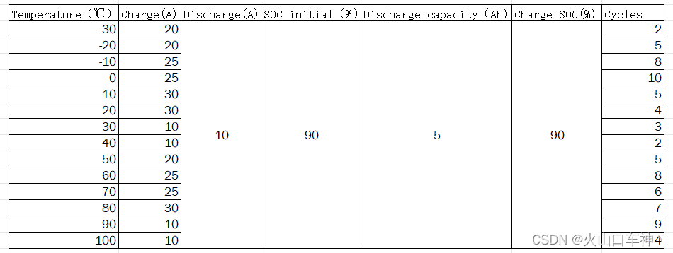
There has to be a 30 seconds pause after each charge and discharge.
Take the first raw as an example to explan:
The initial value of the small battery's SOC is 90%, the temperature is -30℃, and? at the moment, the battery need to discharge with a constant value 10A, when the discharge capacity reaches 5Ah, then the MOS or relay state must change from discharge to charge. And the charge current is 20A until the SOC reaches 90%. All the above procedure is treat as the number 1 cycle, the total cycles is 2 cycles.
And in the other rows, temperature is different,works on the same way. Base on the situation so that the module is able to be developed.
03--SW develop
1--Single temperature value
In order to develop the module,first of all, because of the temperatures are not continuous value, and other parameters change too. We can consider to use stateflow module to make a quick development.
As we had mentioned before,take the first raw as example:
(The charge is represented by a negative number)
Calibration parameters:
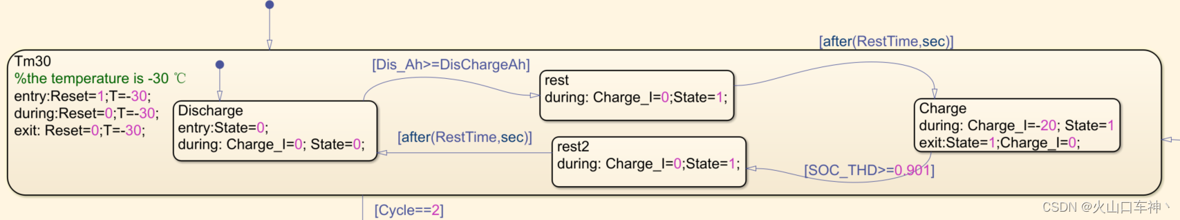
This one stateflow means in the temperature of -30℃,
Reset:use for the cycle number counts,when the total cycles reaches 2,the cycle counts will reset to the value 0.
State: 0 means in the discharge state, 1 means in the charge state.
Charge_I: charge current in the charge state.
Dis_Ah: discharge capacity in 1 cycle
DisChargeAh: constant value 10
RestTime: because of the phrase “There has to be a 30 seconds pause after each charge and discharge.”,so it's constant value 30
SOC_THD: current percentage of SOC
Cycle: the repeat number of cycles
T: temperature
2--Multiple temperature values
The stateflow can in the same way to copy with different temperatures:

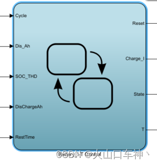
And here are the interface of the stateflow:
3--Current select function
The function generates the value of current
Outside view:
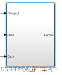
Inside:
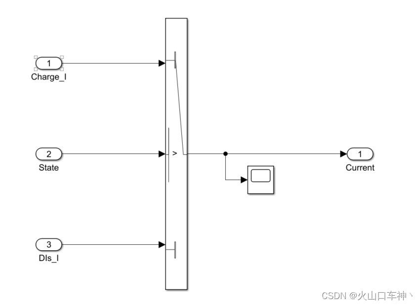
The value of current is impact by the State if it's on charge state or discharge state.
4--SOC calculate function
Outside view:

Inside:

We use the simplest way to calculate the percentage of SOC.
????????????????????? SOC = init_SOC - current*time/capacity
init_SOC: the initial value of SOC
DT: the module sample time
5--Total discharge capacity function
We can calclate the whole discharge capacity
Outside view:

Inside:

We use a Switch module to ignore the charge current, when in the charge state, the total discharge capacity will not be accumulated.
5.1discharge capacity in every cycle:
Outside view:

Inside:

In one cycle the discharge capacity will accumulate by one to one sample time,but in the next cycle, the capacity will reset to value 0.
6--TotalCycle Counter function
Outside view:

Inside:
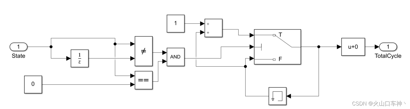
6.1--Cycle Counter function
Outside view:

Inside:

7--Overview
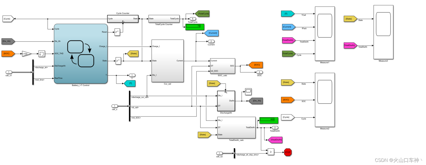

According to the table, we can calculate the total discharge capacity in all the cycles and temperatures.
discharge_ah_stop_simu = (2+5+8+10+5+4+3+2+5+8+6+7+9+4)*5 = 390
We set the value to 390.1, when the capacity reached, the simulation will stop.

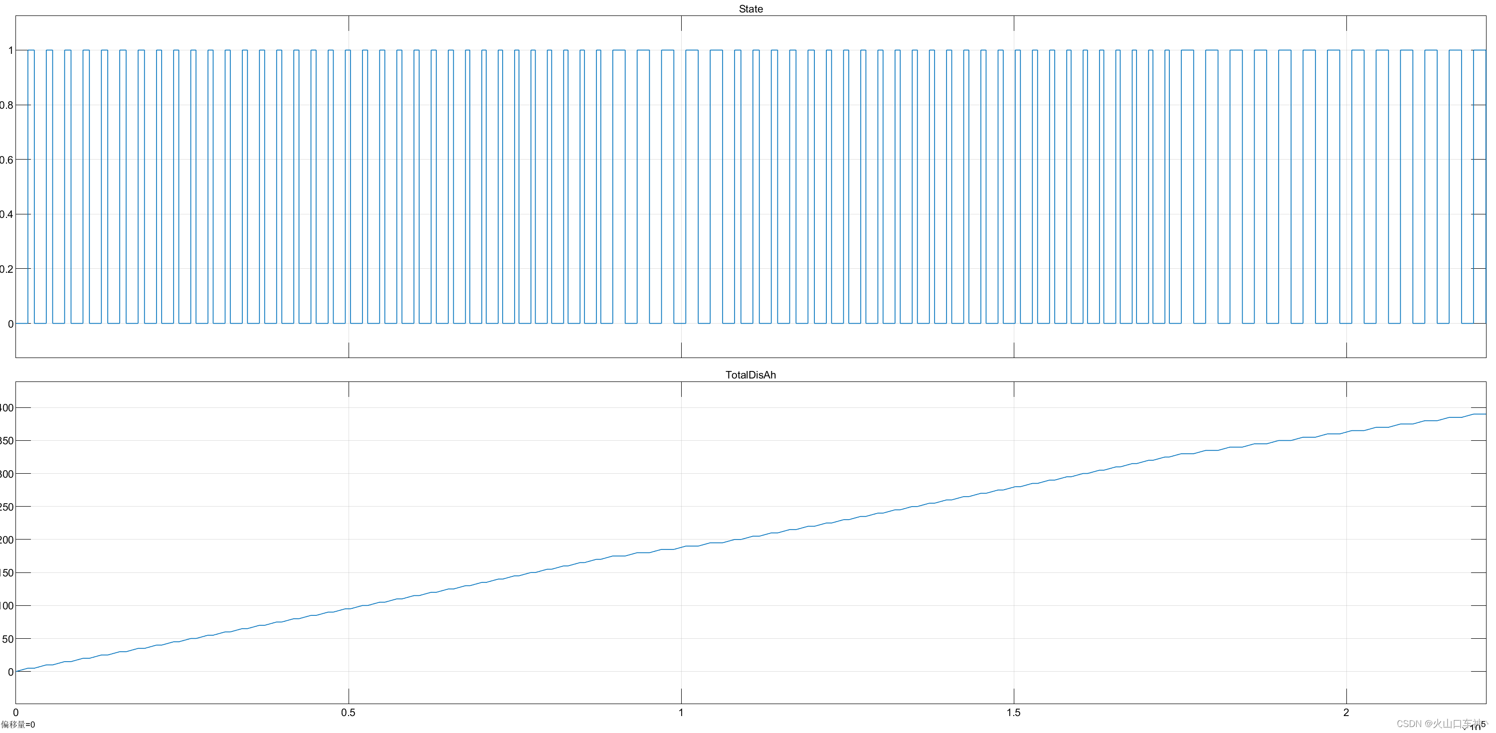
8--Oscilloscope result
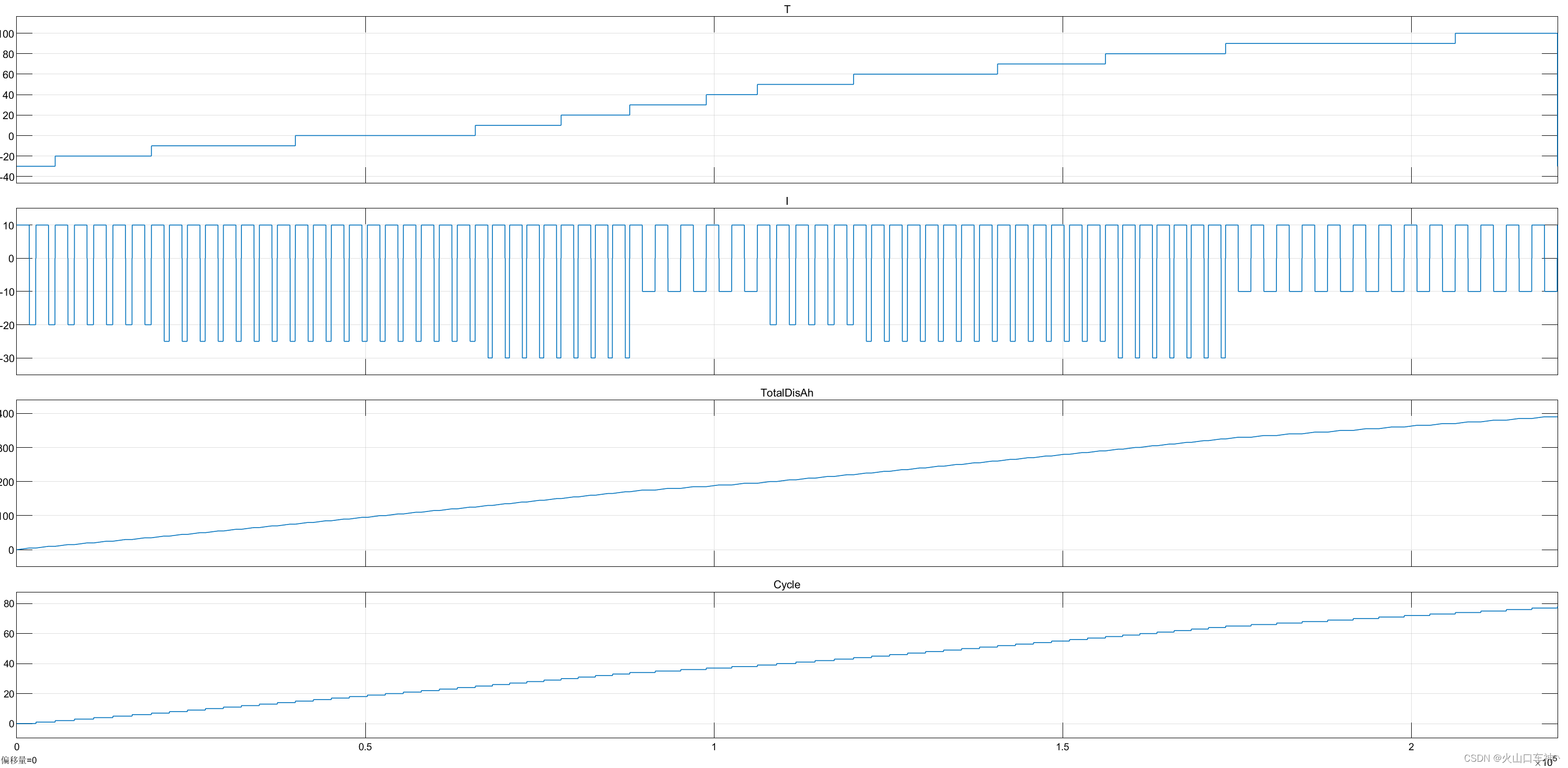
The temperature and current is synchronously changing
The total discharge capacity is 390
Total cycles are 78

Cycle Counter function
Current select function
The details you can see the attachment of the simulink module.
本文来自互联网用户投稿,该文观点仅代表作者本人,不代表本站立场。本站仅提供信息存储空间服务,不拥有所有权,不承担相关法律责任。 如若内容造成侵权/违法违规/事实不符,请联系我的编程经验分享网邮箱:veading@qq.com进行投诉反馈,一经查实,立即删除!